Configuring the 685B-Series
Internal Diagram- Models with Triac Relays
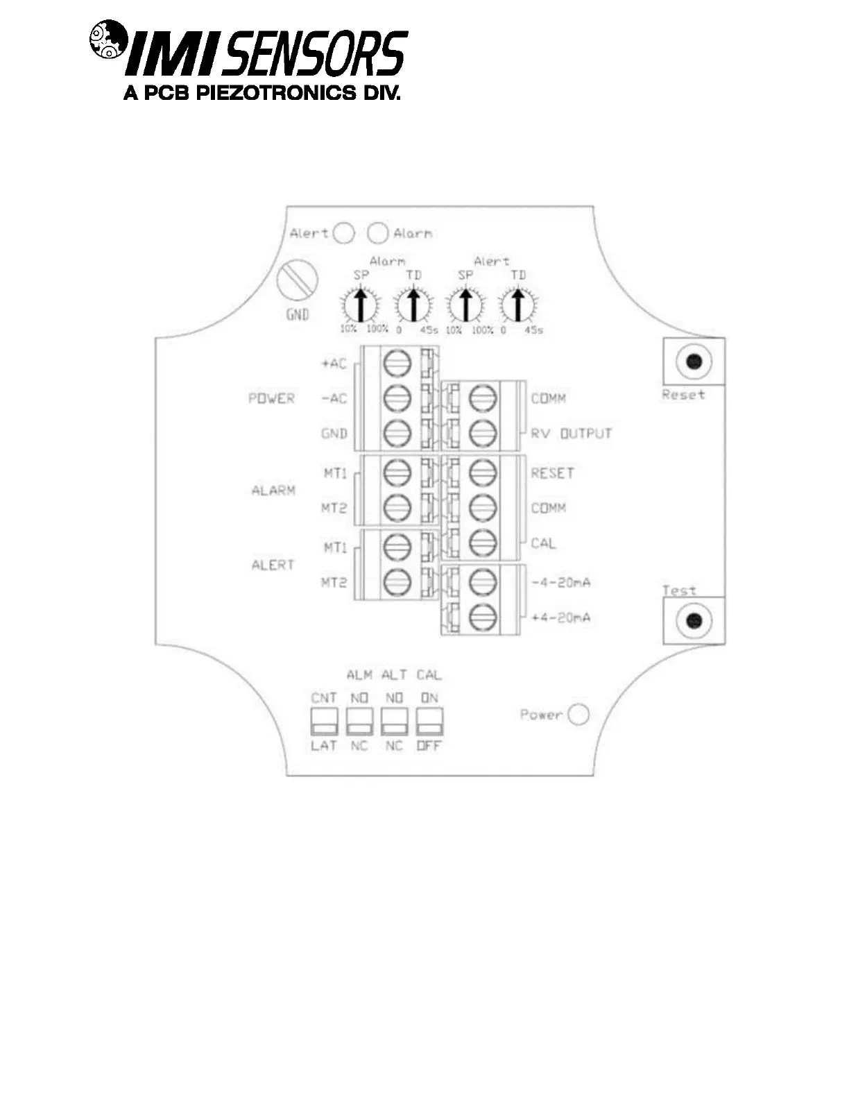
The internal diagram displays the location of the control features for the triac versions of the 685B-Series. The
alert and alarm set points are adjusted via the single turn potentiometers. The alarm relay is set using the first
potentiometer, and the alert relay is set using the third. The alert relay trips when the set percentage of the alarm
value is reached. Time delays for both functions are controlled using the second and fourth potentiometers. Alert
and alarm relays can be reset remotely by using the RESET and COMM pins or by using the internal reset switch
as seen on the upper right hand corner of the diagram.
Using the dipswitches beneath the terminal connectors, relay operation can be selected to be either latch or
continuous, and each relay can be separately configured to be normally open (de-energized) or normally closed
(energized). There is also a dipswitch to activate the calibration mode for condition simulation during the setup
process. This is explained in detail on page 13.
 Loading...