EasyManuals Logo

PCB Piezotronics IMI SENSORS 685B0000A10 User Manual

Default Icon
25 pages
To Next Page IconTo Next Page
To Previous Page IconTo Previous Page
Page #15 background imageLoading...
Page #15 background image
PAGE 10
SENSORS AND INSTRUME
NTATION FOR MACHINE
CONDITION MONITORING
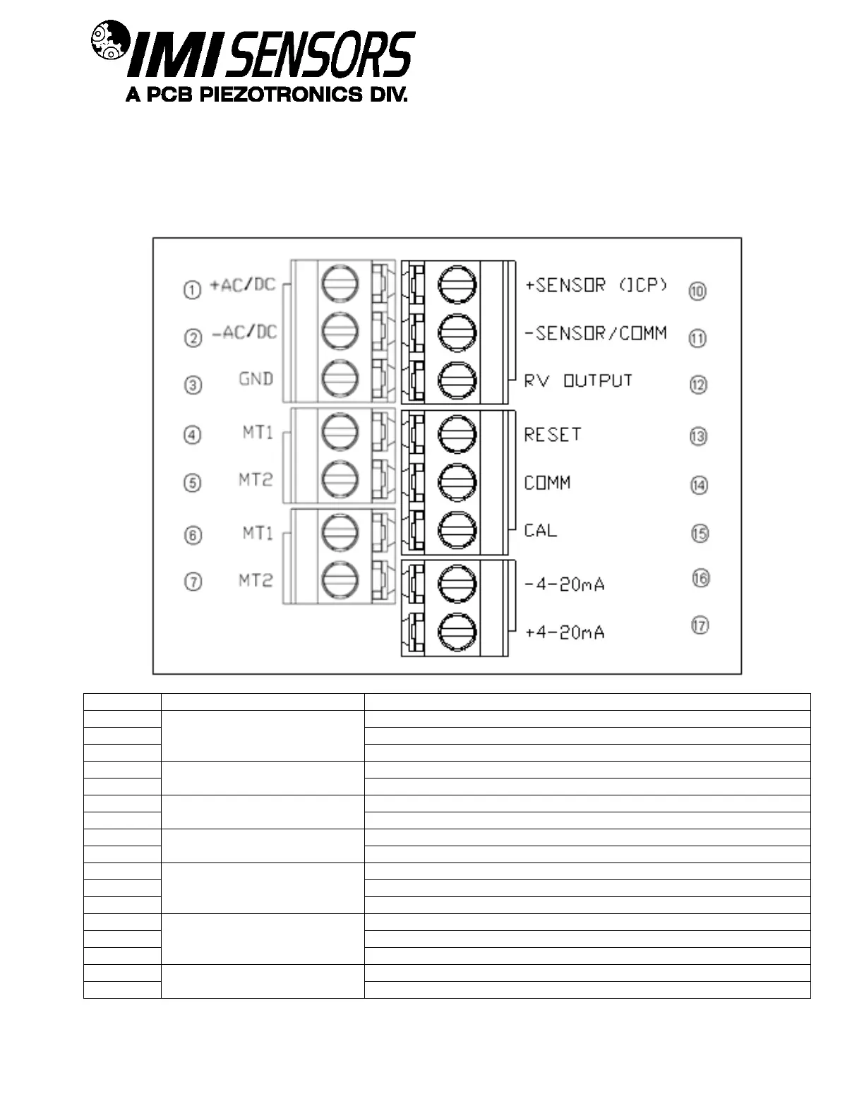
Pin Location Diagram- Models with External Accelerometer and Triac Relays
When the external 100mV/g ICP
®
sensor option is specified, an additional terminal block location is added to the
685B-Series. The external accelerometer is connected to +Sensor and Sensor positions as indicated in the
above figure and on the product label locate inside the top cover. The cable shield to the accelerometer should be
grounded as required by local codes as well as to limit RFI/EMI interference.
Pin
Category
Description
1
AC Power
+ Power
2
- Power/Common
3
Earth Ground (Also connect to enclosure safety lug)
4
Alarm Output
Main Terminal 1
5
Main Terminal 2
6
Alert Output
Main Terminal 1
7
Main Terminal 2
8
N/A
N/A
9
N/A
10
Sensor Input &
Raw Vibration Output
+ Sensor
11
- Sensor/Common
12
+Signal
13
Control Configurations
Remote Reset Connection (Do not apply power)
14
Common Connection
15
Calibration Connection
16
Current Output
- 4-20 mA
17
+ 4-20 mA

Questions and Answers:

Question and Answer IconNeed help?

Do you have a question about the PCB Piezotronics IMI SENSORS 685B0000A10 and is the answer not in the manual?

PCB Piezotronics IMI SENSORS 685B0000A10 Specifications

General IconGeneral
BrandPCB Piezotronics
ModelIMI SENSORS 685B0000A10
CategorySwitch
LanguageEnglish