2: Mainboard Installation
To install a module, push the retaining latches at either end of the
socket outwards. Position the memory module correctly and insert
it into the DIMM socket. Press the module down into the socket so
that the retaining latches rotate up and secure the module in place
by fitting into notches on the edge of the module.
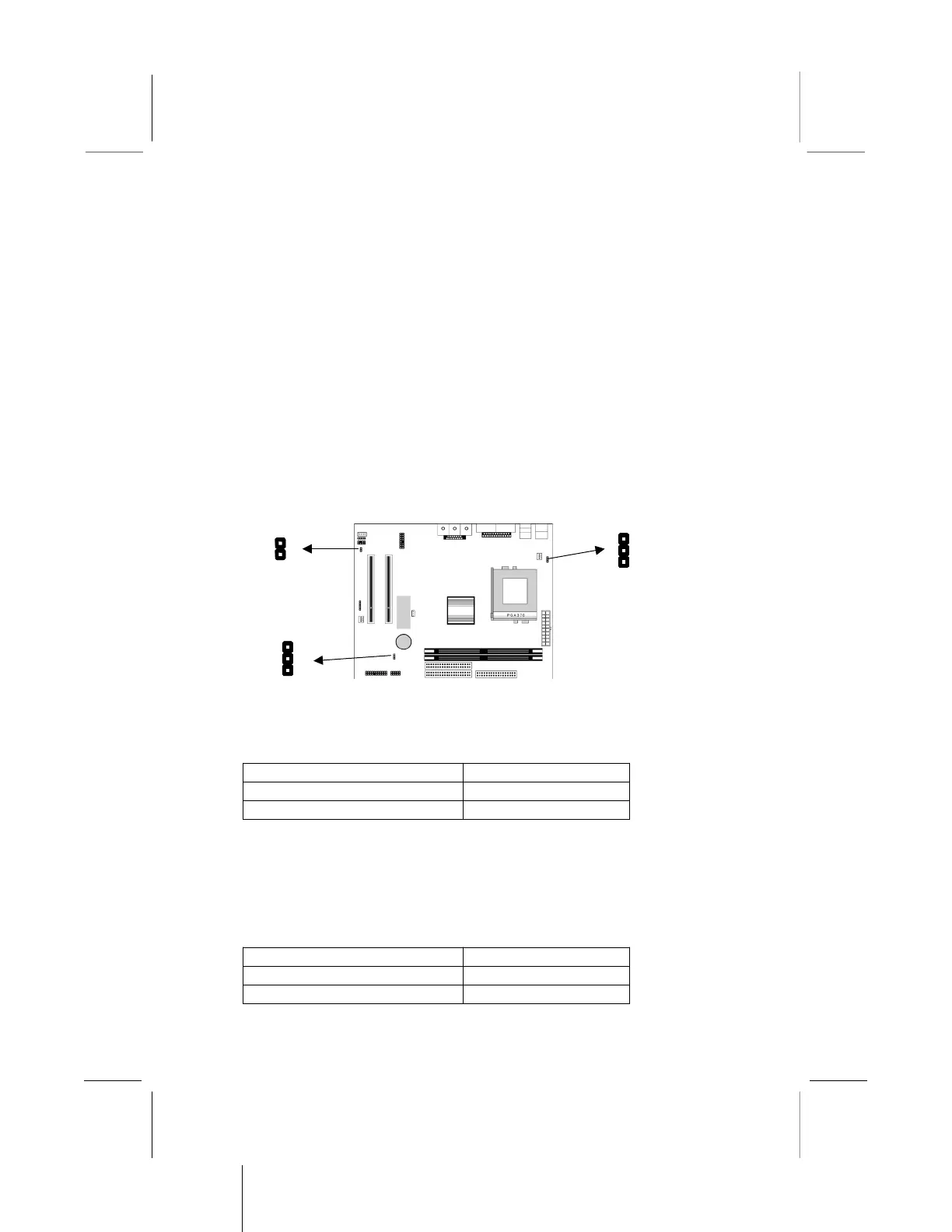
Setting Jumper Switches
Jumpers are sets of pins which can be connected together with
jumper caps. The jumper caps change the way the mainboard
operates by changing the electronic circuits on the mainboard. If a
jumper cap connects two pins, we say the pins are SHORT. If a
jumper cap is removed from two pins, the pins are OPEN.
Jumper JP1: Enable/Disable Fax/Modem
Use this 2-pin jumper to enable or disable the onboard Fax/Modem
connector.
Function Jumper Setting
Disable Onboard Modem Short Pins 1-2
Enable Onboard Modem Open Pins 1-2
Jumper JP5: Keyboard Power On Selector
If you enable the keyboard power on feature, you can use hot keys
on your keyboard as a power on/off switch for the system.
Note: The system must provide 1A on the +5VSB (+5V Standby)
signal before using the Keyboard Power On function.
Function Jumper Setting
Disable Keyboard Power On Short Pins 1-2
Enable Keyboard Power On Short Pins 2-3