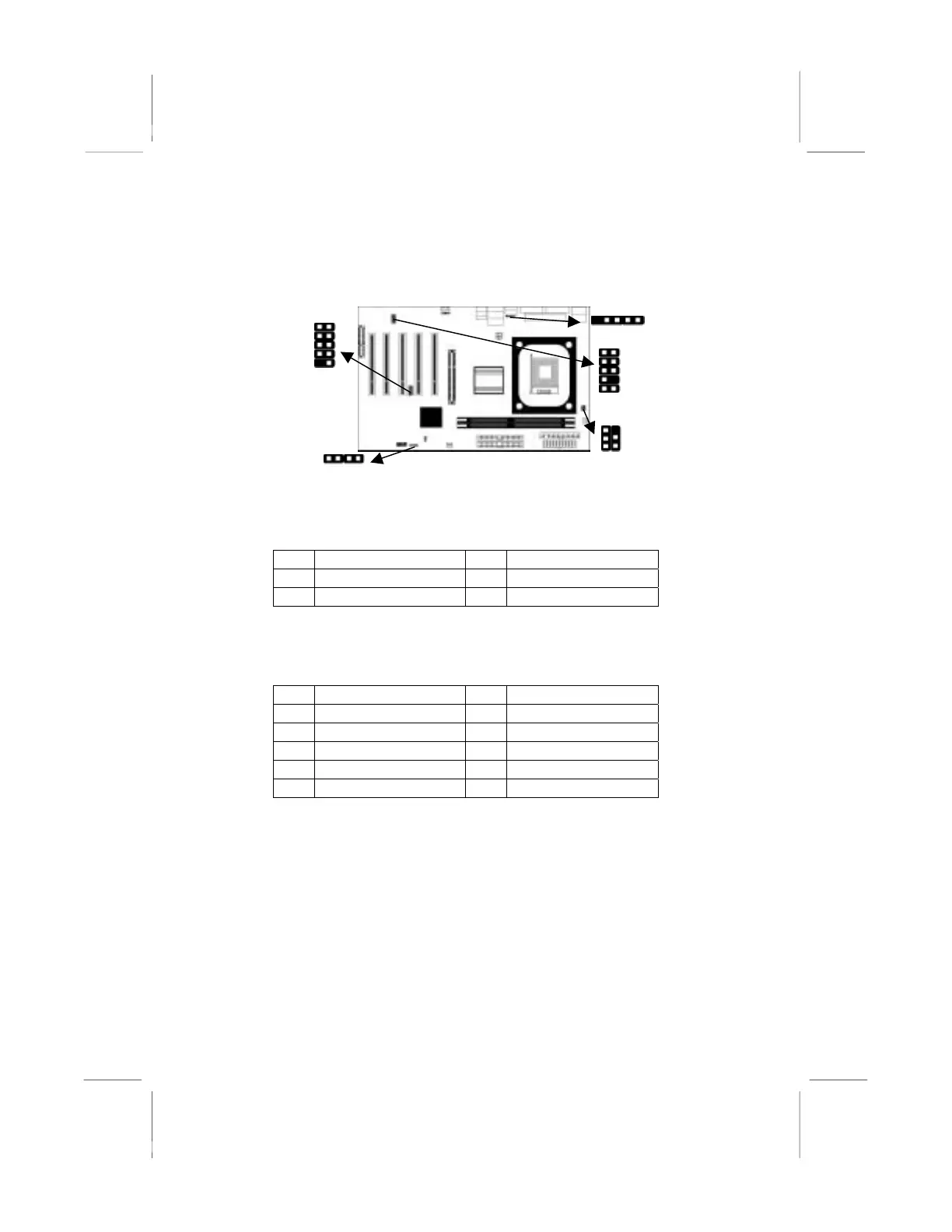
Connecting Optional Devices
Refer to the following for information on connecting the
mainboard’s optional devices:
JUSB1
UDIO2
1
READ1
1
1
1
1
SPK1
SPK1: Speaker Connector
Connect the cable from the PC speaker to the SPK1 header on the
mainboard.
Pin Signal Pin Signal
1 SPKR 2 NC
3 GND 4 +5V
AUDIO2: Front Panel Audio Header
This header allows the user to install auxiliary front-oriented
microphone and line-out ports for easier access.
Pin Signal Pin Signal
1 AUD_MIC 2 AUD_GND
3 AUD_MIC 4 AUD_VCC
5 AUD_FPOUT 6 AUD_RET_R
7 NC 8 KEY
9 AUD_FPOUT 10 AUD_RET_L
JUSB1: Front panel USB Connector
The mainboard has USB ports installed on the rear edge I/O port
array. Additionally, some computer cases have USB ports at the
front of the case. If you have this kind of case, use auxiliary USB
connector USB3 to connect the front-mounted ports to the
mainboard.
13