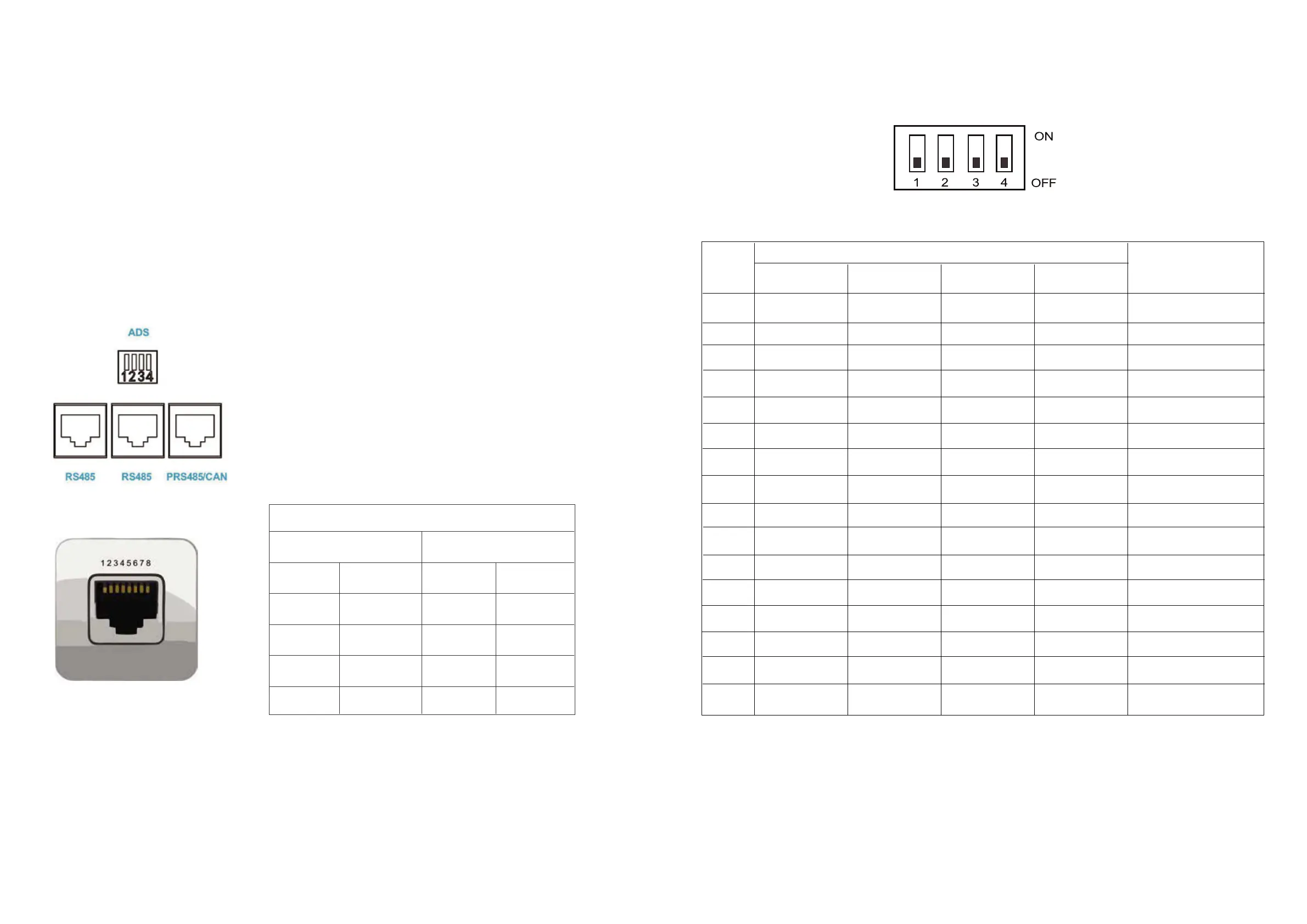
6.2 Communication address selection specification
address
Code switch position
Illustrate
Stand-alone use,
no cascade
OFF OFF OFF OFF0
1# 2# 3# 4#
Set to Pack 1 (Host)
1 OFF OFF OFF
ON
Set to Pack 2
2 OFFOFFOFF
ON
Set to Pack 3
3 OFFOFF
ONON
Set to Pack 4
4 OFFOFFOFF
ON
Set to Pack 5
5 OFF
OFFON ON
Set to Pack 6
6 OFFOFF
ON ON
Set to Pack 7
7 OFF
ON ON ON
Set to Pack 8
8 OFF OFF OFF
ON
Set to Pack 10
10 OFFOFF
ON ON
Set to Pack 9
9 OFF OFF
ONON
Set to Pack 11
11 OFF
ON ON ON
Set to Pack 12
12 OFFOFF
ON ON
Set to Pack 13
13 OFF
ONON ON
Set to Pack 14
14 OFF
ONONON
Set to Pack 15
15
ON ON ON ON
13 14
RS485
PRS485/CAN
RS485-B
RS485-A
1、8 1、8
2、7 2、7
RS485-B
RS485-A
4
5
CAN-H
CAN-L
6.BMS communication settings
6.1 BMS communication and setting
When the load (such as inverter) needs to communicate with the battery,
in order to establish normal communication with the load, BMS needs to set
the following settings for each brand. The RS485 communication protocols of
inverters are different,but there are several RS485 communication protocols
inside the inverter to match the battery. When using,you can directly select
the communication protocol code in the inverter for matching. If you have
other problems, please consult the supplier.
Battery BMS interface pin foot definition as shown in the following figure
The battery communication interface adopts 8P8C RJ45 socket.
PIN Definition PIN Definition
“ADS” is used for parallel use of battery packs.
PACK can be distinguished by hardware address.
The definition of ADS master-slavead dress refers to
communication address selection specification.
“PRS485/CAN” battery pack can communicate with the
upper computer or inverter and the reverse control
integrated machine through the interface.
“RS485” is used in parallel for battery pack,and
the main communicates with pack from the interface.


 To Next Page