65
L510010-11
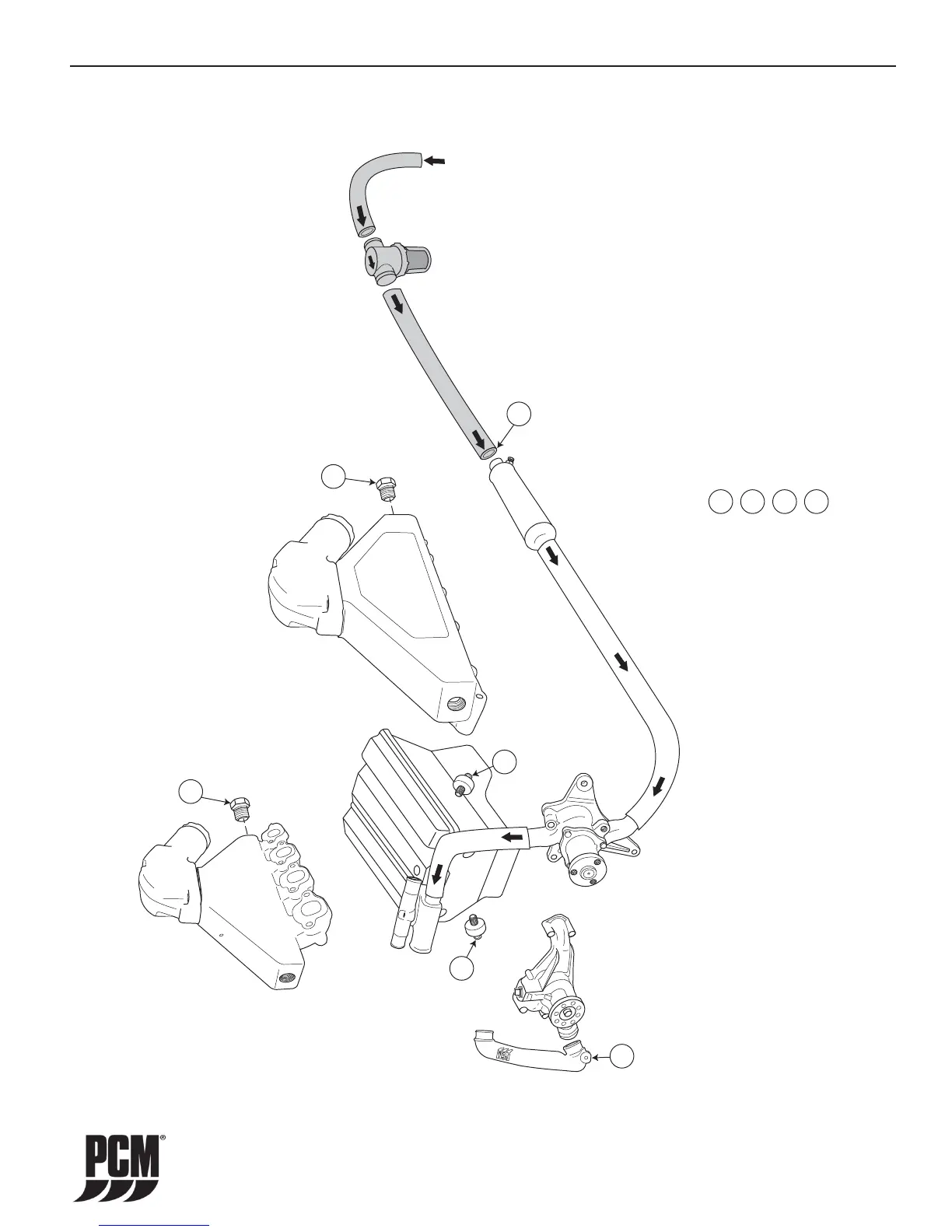
WATER FLOW DIAGRAMS - 15
From Sea
Water Pickup
Note: This diagram is for illustration purposes
only. The actual routing and/or shape of the hoses
may vary slightly depending on installation.
1
1
1
2
2
3
3
3
4
4
Drain Locations
- Engine Block Drains - Remove Knock Sensors
- Engine Circulating Water Pump Pipe - Remove Drain Plug
- Exhaust Manifolds - Remove Drain Plugs
- Transmission Cooler - Remove Inlet Hose
Figure 15-1 Direct Drive Raw-Water Cooling System HO303 / EX343
 Loading...