Basic Component Testing
Basic Comvonent Testing
Computer Controlled Systems Cont 'd..
.
Computer Controlled Systems Cont 'd..
.
Basic Daignostics for the Computer
Controlled Engine
There are two important steps that must always be followed when
diagnosing and repairing vehicles with computer controls.
Do basic engine diagnostics first. Many problems can be traced to
lack of routine maintenance on components such as plug wires,
filters and spark plugs. Also check for vacuum leaks on any vehicle,
new or old.
A
complete engine diagnosis should precede any
electrical system diagnostics.
Follow the published Diagnostic Charts EXACTLY through every
step to make a repair on a computer component.
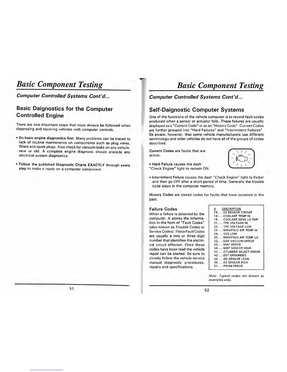
Self-Daignostic Computer Systems
One of the functions of the vehicle computer is to record fault codes
produced when a sensor or actuator fails. These failures are usually
displayed as a "Current Code" or as an "History Code". Current Codes
are further grouped into "Hard Failures" and "Intermittent Failuresn.
Be aware, however, that some vehicle manufacturers use different
terminology and older vehicles do not have all of the groups of codes
described.
Current Codes are faults that are
f
\I/>
active.
Hard Failure causes the dash
"Check Engine" light to remain ON.
'I'
Intermittent Failure causes the dash "Check Engine" light to flicker
and then go OFF after a short period of time. Generally the trouble
code stays in the computer memory.
History Codes are stored codes for faults that have occurred in the
past.
Failure
Codes
When a failure is detected by the
computer,
it
stores the informa-
tion in the form of "Fault Codes"
(also known as Trouble Codes or
Service Codes). These Fault Codes
are usually a two or three digit
number that identifies the electri-
cal circuit effected. Once these
codes have been read the vehicle
repair can be started. Be sure to
closely follow the vehicle service
#
DESCRIPTION
-
13
......
02
SENSOR
CIRCUIT
14
......
COOLANT
TEMP
HI
15
......
COOLANT
SENS
LO
TMP
21
......
TPS
VOLTAGE
HI
22
......
TPS
VOLTAGE
LOW
23
......
MANIFOLD
AIR
TEMP
HI
24
......
VSS
LOW
25
......
MANIFOLD
AIR
TEMP
LO
32
......
EGR
VACUUM
ERROR
33
......
MAP
ERROR
34
......
MAP
SENSOR
HIGH
41
......
CYLINDER SELECT
ERROR
42
......
EST GROUNDED
I
44
......
OS
SENSOR
LEAN
manual diagnostic precedures,
45
......
02
SENSOR
RIGH
repairs and specifications.
51
......
PROM
ERROR
L
Note: Typical codes
are
shown as
examples only.
 Loading...