Basic Diagnostic Testing
Basic Diagnostic Testing
Battery Testing
Con
t
'd..
.
Voltage Drop Testing
[4]
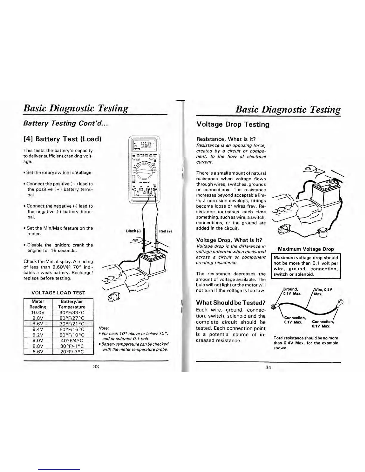
Battery Test (Load)
This tests the battery's capacity
to deliver sufficient cranking volt-
age.
Set the rotary switch to Voltage.
Connect the positive
(
+
1
lead to
the positive
(
+
1
battery termi-
nal.
Connect the negative
(-1
lead to
the negative
(-1
battery termi-
nal.
Set the MiniMax feature on the
meter.
Disable the ignition; crank the
engine for
15
seconds.
Checkthe Min. display.
A
reading
of less than
9.60V@
70°
indi-
cates a weak battery.
Recharget
replace before testing.
VOLTAGE LOAD TEST
Note:
For each
10
O
above or below
70
O,
add or subtract
0.1
volt.
Battery temperature can
be
checked
with the meter temperature probe.
Resistance, What
is
it?
Resistance is an opposing force,
created
by
a circuit or compo-
nent, to the flow of electrical
current.
There is a small amount of natural
resistance when voltage flows
through wires, switches, grounds
or
connections. The resistance
lncseases beyond acceptable lim-
crs
if
corrosion develops, fittings
become loose or wires fray. Re-
sistance increases each time
something, such as wire, a switch,
connections,
or
the ground are
added in the circuit.
Voltage
Drop,
What
is
it?
Voltage drop
is
the difference in
voltage potential when measured
Maximum
Voltage
Drop
across a circuit or component
creating resistance.
The resistance decreases the
amount of voltage available. The
not
be
more than
0.1
volt per
wire, ground, connection,
bulb will not
liaht or the motor will
-
not turn if the voltage is too low.
Ground,
Wlre,
0.1V
p.1~
M.X.
ax.
What Should be Tested?
Each wire, ground, connec-
tion, switch, solenoid and the
#
Connection,
complete circuit should
he
0.1
v
Max.
Connection,
tested. Each connection point
0.1V Max.
is a potential source of in-
creased resistance.
Total resistance should be no more
than
0.4V
Max. for the example
shown.