Basic
Component Testing
Component Tests (Input) Con
t
'd..
.
Thermistor (Variable Resistance,
2-
wire) Tests Con 't..
.
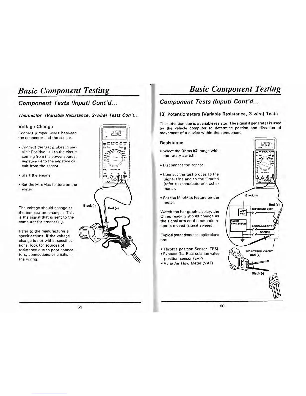
Voltage Change
Connect jumper wires between
the connector and the sensor.
Connect the test probes in par-
allel: Positive
(
+
)
to the circuit
coming from the power source,
negative
(-1
to the negative cir-
cuit from the sensor.
Start the engine.
Set the MinIMax feature on the
meter.
Black
(-)
The voltage should change as
the temperature changes. This
is the signal that is sent to the
computer for processing.
Refer to the manufacturer's
specifications. If the voltage
change is not within specifica-
tions, look for sources of
resistance due to poor connec-
tors, connections or breaks in
the wiring.
Basic Component Testing
Component Tests {Input) Con t
'd..
.
[3]
Potentiometers (Variable Resistance, 3-wire) Tests
The potentiometer is a variable resistor. The signal
it
generates is used
by
the vehicle computer to determine postion and direction of
movement of a device within the component.
Resistance
Select the
Ohms
(a)
range with
the rotary switch.
Disconnect the sensor
Connect the test probes to the
Signal Line and to the Ground
(refer to manufacturer's sche-
matic).
Set the MintMax feature on the
/
Black
(-)
I
meter.
Watch the bar graph display; the
Ohms reading should change as
the signal arm on the potentiom-
eter is moved (signal sweep).
Typical potentiometer applications
are:
Throttle position Sensor (TPS)
/
TPS
INTERNAL
CIRCUIT
Exhaust Gas Recirculation valve
position sensor
(EVP)
Vane Air Flow Meter WAF)
~-
Black
(-)