Basic Component Testing
Specifications
Component Tests (Output)
General Specifications
Output Devices
The electrical tests for output devices vary greatly, depending upon
type and manufacturer. Consult the vehicle service manual for the
schematic, specifications and test procedures.
Primary output devices (actuators) are a form of an electromagnet
that is either ON or OFF. The
ONIOFF signal, in general, will be in one
of three configurations:
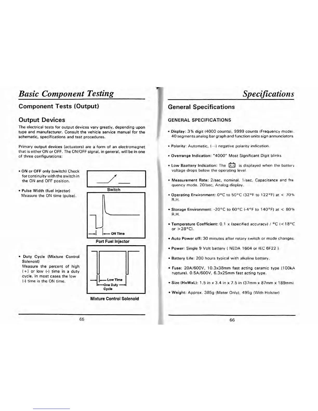
ON
or
OFF
only (switch) Check
for continuity with the switch in
the ON and OFF position.
Pulse Width (fuel injector)
Measure the ON time (pulse).
Duty Cycle (Mixture Control
Solenoid)
Measure the percent of high
(+)
or low
(-)
time in a duty
cycle. In most cases the low
(-1
time is the ON time.
GENERAL SPECIFICATIONS
Display: 3% digit (4000 counts), 9999 counts (Frequency model.
40 segments analog bar graph and function units sign annunciators
Polarity: Automatic,
(-1
negative polarity indication
Overrange Indication: "4000" Most Significant Digit blinks
Low Baattery Indication: The
is displayed when the
batterv
voltage drops below the operating level.
Measurement Rate:
2/sec, nominal.
1
Isec, Capacitance
and
fre-
quency mode.
20/sec, Analog display.
Switch
Operating Environment: O°C to 50°C (32OF to 122OF) at
<
70%
R.H.
Storage Environment: -20°C to 60°C (-4OF to
1
40°F) at
<
80%
R.H.
I
Port
Fuel
Injector
+:;:A
cycle
Temperature Coefficient: 0.1 x (specified accuracy)
/
OC
(<
18OC
or >28OC).
Auto Power off: 30 minutes after rotary switch or mode changes.
Power: Single
9
Volt battery
(
NEDA 1604 or IEC 6F22
1.
Battery Life: 200 hours typical with alkaline battery.
Fuse: 20A/600V, 10.3x38mm fast acting ceramic type (100kA
rupture). 0.5A/600V, 6.3x25mm fast acting type.
Size (HxWxL): 1.5 in x 3.4 in x 7.5 in (37mm
x
87mm x 189mm).
Weight: Approx. 3859 (Meter Only), 4959 (With Holster!
Mixture Control Solenoid