www.pdr-rework.com
Principles of Operation (continued)
Iris Assembly
The iris assembly is located between the upper lens assembly and the lens attachment, and serves in conjunction with
the lens attachment, to vary the diameter of the I.R. beam spot size to suit the component to be removed.
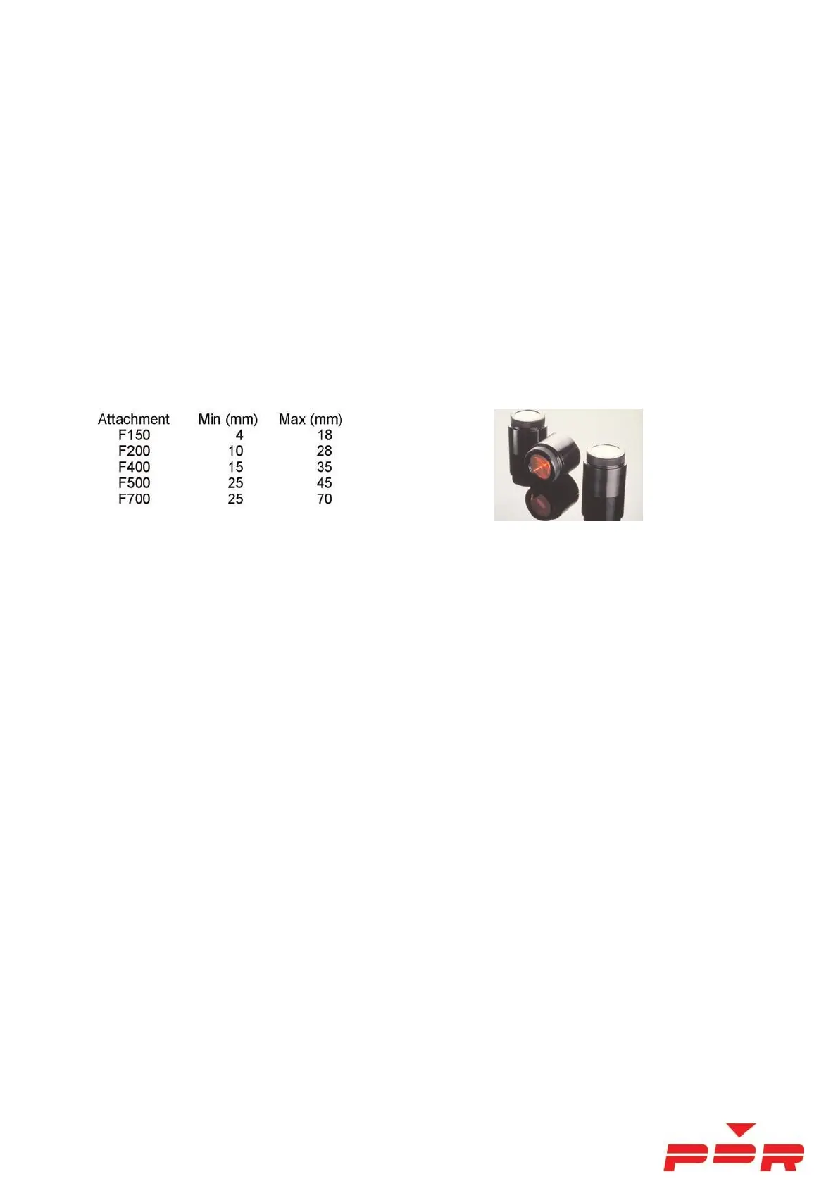
Lens Attachments
The lens attachment focuses the beam into a spot. The spot size is determined by the divergence angle of the lens
attachment. A range of interchangeable lens attachments are available to cater for different sizes of component.
The selection of the lens and spot size should allow for approximately a 5-10mm overlap of the component. The
minimum and maximum spot size of the lens attachments are as follows:
A frequency selective filter is fitted to the underside of the lens attachment to reduce the amount of visible light
passed. The remaining red light is at a level which is comfortable for operator viewing and allows the user to view the
spot.
Back Heat (PCB Preheater)
The back heat is applied by a 750 – 3000w medium-wave Quartz IR emitter controlled by the software/digital
controller and performs three functions:
1. It preheats the PCB and also helps avoid overheating the component.
2. It reduces the risk of thermal shock and PCB de-lamination (PCB blistering)
3. It counteracts the heat sink effect of heavy tracking in the PCB.
The PCB preheater consist of quartz IR heaters preheating the PCB and the heat conducts through the PCB and
preheats the component, so when you introduce the Top Heat there is no chance of thermal shock. The balance of
heat energy supplied should be approximately 75 % from the Back Heater and 25 % from the Top Heat.
Thermocouples (T/C)
Up to four thermocouples (T/Cs) can be used and displayed. Only T/C 1 and 2 are used for control. T/C 3 and 4, if
selected are only used for additional temperature information.
(Note: To use PCB Preheat/backheat T/C #2 must be plugged into its socket even if it is not used. If it is not plugged in
the controller will sense a sensor ‘break’ and will switch off the backheater)
 Loading...