5.
Install the license plate screws to secure the camera to the vehicle.
6. Determine which are the positive (+) and negative (-) wires for the reverse lights on the vehicle.
You can use either the right- or left-side reverse light wires. For help locating the vehicle’s reverse
light circuit, contact your vehicle’s manufacturer for vehicle-specifi c wiring diagrams.
7. Remove the vehicle’s negative (-) battery cable.
8. Once the proper wires for the reverse lights have been determined, the transmitter wires must
be spliced into the vehicle wires using the supplied wire connectors. If you choose to wire
the transmitter using a different method, you must be knowledgeable in 12-volt DC electrical
practices.
+
2
3
7
6
8
3
5
1
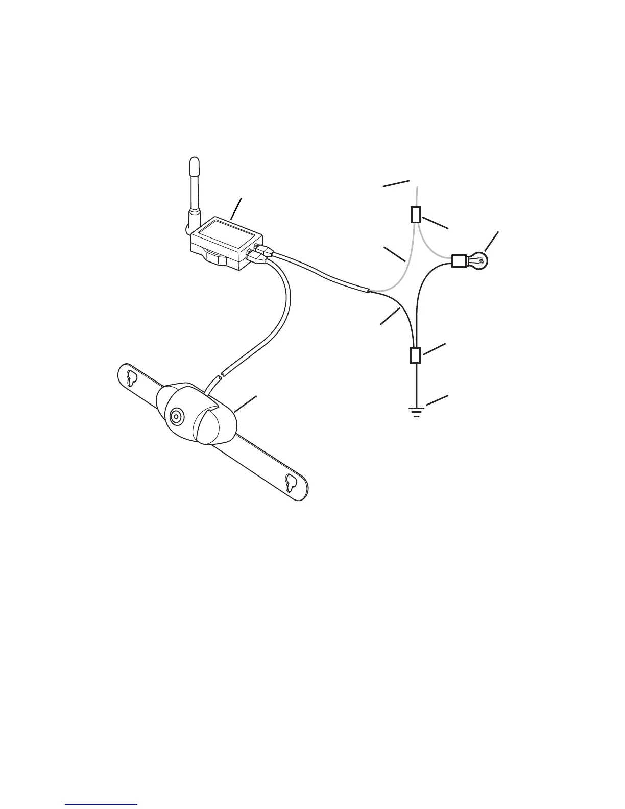
Legend
1.
Transmitter
2. Positive (+) Wire from Reverse Light
3. Wire Connector
4. Reverse Light
5. Negative (-) Wire from Reverse Light
6. Negative (-) Transmitter Power Wire (Black)
7. Positive (+) Transmitter Power Wire (Red)
8. Camera
9. The red positive (+) wire from the transmitter splices into the positive (+) wire from the reverse
lights and the black negative (-) wire from the transmitter splices into the negative (-) wire from
the reverse lights.
10. Position the connector around the vehicle wire you are splicing into.
11. Slide the appropriate wire from the transmitter into the connector.