PCAN-USB (ISO) – User Manual
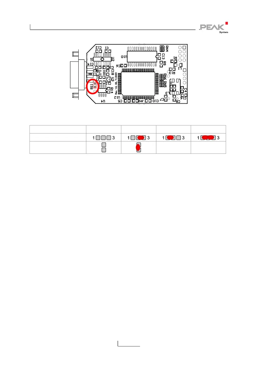
Figure 3: PCB PCAN-USB ISO, R11
5-Volt supply →
None Pin 1 Pin 9 Pin 1 + Pin 9
PCAN-USB, JP3
PCAN-USB ISO, R11
-/- -/-
3. For reassembly place the PCB overhead onto the top part of
the case. Make sure that the cable is lying with the strain
relief in the cut-out of the case, and that the LED is placed in
the corresponding hole.
4. Push the bottom part of the case onto the top part (the
latches click in).
10