PCAN-USB (ISO) – User Manual
Attention! Risk of short circuit! If the option described in this
section is activated, you may only connect or disconnect CAN
cables or peripheral systems (e.g. external transceivers or
optocouplers) to or from the PCAN-USB adapter while it is de-
energized (the adapter is not connected to the PC). Consider
that some PCs still supply the USB ports with power even when
they are turned off (standby operation).
Important note: PEAK-System Technik GmbH does not give
guarantee on damages which have resulted from application of
the option described in this section.
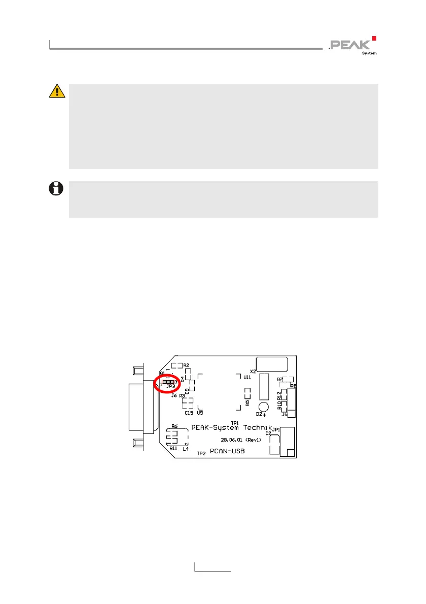
Procedure:
1. In order to access the PCB, open the case of the PCAN-USB-
Adapters by cautiously pushing in the latches on both sides
(risk of breakage!), e.g. with a flat tip screwdriver.
2. Set the solder bridge on the PCB of the PCAN-USB adapter
according to the desired function. Figure 2 and Figure 3
show the position on each PCB; the table below contains the
possible settings.
Figure 2: PCB PCAN-USB, JP3
9