The
DC
current
range
s
of
the
instrument
are namely 600µA,
6000µA, 60.00mA, 600.0mA, 6.000A
and
10
.00A.
The
AC
current
ranges
are namely 600µA, 6000µA, 60.00mA,
600.0mA, 6.000A
and
10.00A;
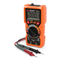
Measure current:
1. Turn
the
rotary switch
to
a
proper
gear,
and
press
the
"SEL"
key
to
switch
DC
or
AC
current
function.
2.
Connect
the
black
test
pen
to
the
COM
input
socket.
If
the
measured
current
is
less than 600mA,
connect
the
red
test
pen
to
the
µAmA
input
socket;
if
the
measured
current
ranges
from 6A
to
l0A,
connect
the
red
test
pen
to
the
l0A
input
socket.
3. Disconnect
the
circuit
to
be
mea
sured.
Connect
the
black
test
pen
to
one
end
of
the
disconnected
circuit (with
lower voltage),
and
connect
the
red
test
pen
to
one
end
of
the
disconnected
circuit (with
higher
voltage).
4.
Connect
the
power
supply
of
the
circuit,
and
then
read
out
the
reading from
the
display.
If
the
display only
shows
"OL
",
it
indicates
the
input
exce~ds
the
selected
range
,
and
the
rotary switch shall
be
placed in a higher
range
.
Note:
•Under
AC
voltage function, press HZ/% key
to
measure
the
frequency of
AC
current
(0HZ-l0KHZ).
3.2.8 NCV
test
(non-contact
voltage
detection)
Turn
the
rotary switch
to
the
NCV
gear,
and
close
the
instrument
top
to
the
conductor,
if
the
instrument
detects
AC
voltage
,
the
instrument
will
light
up
indicator
of
corresponding
signal
strength
(high, medium and low),
according
to
the
detected
signal
strength
, meanwhile
the
buzzer
will
make alarm
sounds
of
different frequencies.
Note:
1. Even
if
there
's
no
indication,
voltage
may still exist. Do
not
judge
whether
there's
voltage
in
lead
depending
on
~on-
contact
voltage
detector
. Detection
may
be
impacted
by
factors sucti as different socket designs,
and
insulation
thickness types
etc
.
2:
When
inputting
voltage
at
i
nstrument
input
terminal, for
the
existence
of
induced voltage,
the
voltage
sensing indicator
may also light
up
.
3: Interference
sources
from external environment (i.e. flash
light,
motor
etc.),
may
tr
i
gger
non-contact
voltage
detection
by mistake.
4 Technical indicatQrs
4.1
Comprehensive
indicators
Use environmental conditions:
, .
20
21
'
(
I
..
··•·
"'·
·
;.;.
. .
.
-.
~
;}·
. ~ .
..
....
'