47
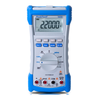
5.4 Measuring Resistance
Warning
Never connect the test leads to a source of voltage when you have
selected the Ohms function and plugged the test lead jack into
V/Ω-terminal. Be sure that the circuit under test has all power
removed and any associated capacitors are fully discharged
before you make a resistance measurement.
Follow these steps to measure resistance:
1. Set the rotary selector to Ω/ /
.
))) position.
2. Plug the black test lead into the meter’s COM terminal and the
red test lead into the V/Ω terminal.
3. Connect the test leads to the object to be measured.
Notes:
* The resistance in the test leads can diminish the accuracy on
the lowest 220 Ω range. The error is usually 1 to 0.2 Ω for a
standard pair of test leads. To determine the error, short the test
leads together and read the resistance of the test leads.
* When measuring resistance, be sure that the contact between
the test leads and the object is good. Dirt, oil, solder flux or other
foreign matters can cause incorrect readings.
* If the measured resistance value exceeds the maximum value,
OL will be displayed indicating overload and bar graph will be
flashing.
* For resistance of approximately 2 MΩ and above, the display
might take a few seconds to stabilize. This is normal for high
resistance readings.
* During resistance measurement, the present measuring value is
in the main display, the measured value taken 1 second earlier
in the left secondary display, the measured value taken 2
second earlier in the middle secondary display and the
measured value taken 3 seconds earlier in the right secondary
display.