Installation of Host Computer and Peripherals
Standalone Installation
3-5
Board/Connector Relationship
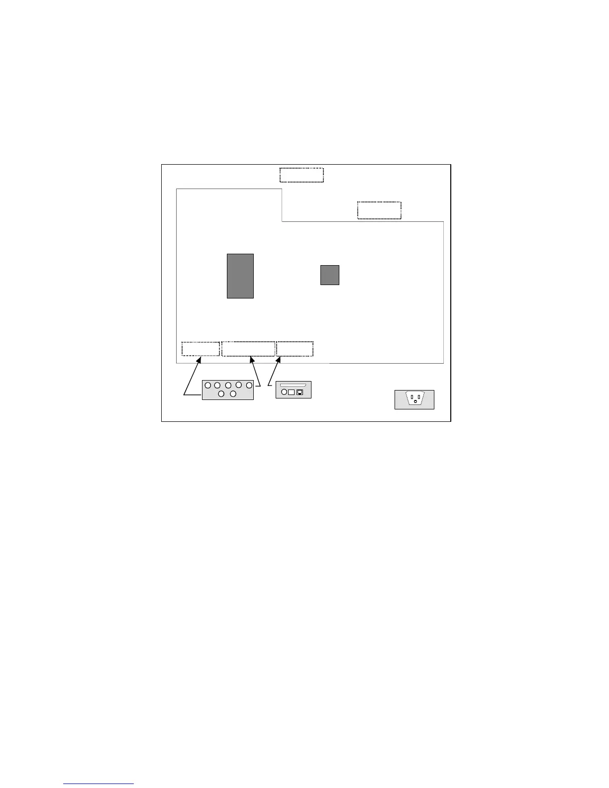
Figure 3-2 illustrates the relationship between PC boards attached to the bulkhead
inside the cabinet and the connectors on the exterior surface of the cabinet.
Note: There is a LINE PRINTER/NETWORK connector on the bottom left side of the
cabinet. Only the LINE PRINTER connector is used in a standalone configuration.
Figure 3-2 Standalone Board/Connector Locations
CAMERA
CONTROLLER
BOARD
SCANNER
CONTROLLER
MAIN BOARD
PRTCON
KEMCON
KEYBOARD MOUSE
MONITOR
No Board Required for
Monitor (Pass Through)
LINE PRINTER
NETWORK
INPUT POWER
 Loading...