(16) EFFECTS SEND LEVEL
This calibrated (0 – 10) control sets the level of signal being sent to external effects
and/or signal processors. Clockwise rotation increases the amount of signal being
sent; counterclockwise rotation decreases the amount. For the quietest operation,
the EFFECTS SEND LEVEL should be set as high as possible. Generally, the SEND and
RETURN levels should be set oppositely. If the EFFECTS SEND LEVEL is set low, the
EFFECTS RETURN LEVEL (19) is set high to achieve unity gain. If volume boost is desired,
turn both controls to higher settings.
(17/18) EFFECTS SEND / EFFECTS RETURN
These 1/4" mono (TS) jacks allow signal to be sent to and returned from external
effects and/or signal processors. Using shielded cables with 1/4" mono (TS) phone
plugs, patch from EFFECTS SEND to the input of the external device, and from the
output of the external device to EFFECTS RETURN. Only devices that do not increase
signal gain should be used in this effects loop (chorus, delay, reverb, etc.). If the
footswitch is used, the EFFECTS SELECTOR (33) switch must be depressed to activate
the effects loop. See the FOOTSWITCH section of this manual for explanation of
switch operation.
(19) EFFECTS RETURN LEVEL
This calibrated (0 – 10) control sets the level of signal being returned from external
effects and/or signal processors. Clockwise rotation increases the amount of signal
being returned; counterclockwise rotation decreases the amount. Again, SEND and
RETURN levels should be set oppositely, with the SEND level being high and the
RETURN level low to ensure the quietest operation. By setting both the Send and
Return higher, you can use the effects button on the footswitch as a boost if you
aren't using the effects loop with effects.
(20) REMOTE SWITCH
This seven-pin DIN connector is provided for the connection of the remote footswitch.
The footswitch cable should be connected before the amp is powered up. See the
FOOTSWITCH section of this manual for explanation of switch operation.
(21) BIAS TEST TERMINALS
These terminals are provided to measure the bias of the amplifier’s power tubes. A
knob behind the back panel grill allows for adjustment. Bias adjustment should only
be done by a qualified technician.
(22) DAMPING SWITCH
This three-position switch allows adjustment of the amplifier’s damping factor.
Damping is the ability of an amplifier to control speaker cone motion after a signal
disappears. A high damping factor (TIGHT) reduces cone vibration quicker than a low
(LOOSE) factor. This switch works much like the resonance and presence controls on
other Peavey amps, if those controls were turned simultaneously. If the DAMPING
SWITCH is changed, the volume of the amp will also change and require re-adjustment.
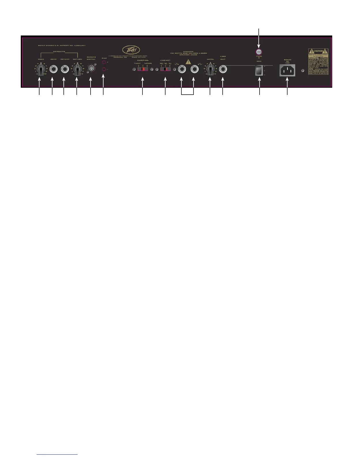
REAR PANEL
16 17 18 19 20 21 22 23 2524 26 28 29
27
7
 Loading...