EasyManua.ls Logo

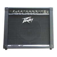
Peavey BANDIT 75

Peavey BANDIT 75
4 pages
To Previous Page IconTo Previous Page
Loading...
BANDIT
75
ENGINEERING
SPECIFICATIONS
POWER
AMPLIFIER
SECTION:
RATED
POWER
&
LOAD:
75
W
RMS
into*8
ohms
POWER
@
CLIPPING:
(Typically)
(5%
THD,
1
kHz,
120
VAC
line)
80
W
RMS
into
8
ohms
4
ohms
not
recommended
FREQUENCY
RESPONSE:
-*0,
-1
dB
20
Hz
to
20
kHz
@
65
watts
into
8
ohms
TOTAL
HARMONIC
DISTORTION:
Less
than
0.5%,
100
mW
to
65
W
RMS,
60
Hz
to
10
kHz,
8
ohms
typically
below
0.2%
HUM
&
NOISE:
Greater
than
95
dB
below
rated
power
POWER
CONSUMPTION:
200
watts,
50/60
Hz,
120
VAC
PREAMP
SECTION:
THE
FOLLOWINGSPECSAREMEASURED@1
kHz
WITH
THE
CONTROLS
PRESET
AS
FOLLOWS:
Push
Bright
Off
(Out)
Channel
Select
(Norm/Out)
SuperSat^Co)
10
Post
Gain
@
10
Low
&
High
@
10
Mid
EO
@
10
Presence
@
0
dB
Reverb
@
0
Nominal
levels
are
with
normal
gain
level
@
5
Minimum
levels
are
with
normal
gain
level
@
10
PREAMP
HIGH
GAIN
INPUT:
Impedance:
High
Z.
220K
ohms
Nominal
Input
Level:
-20
dBv,
100
mV
RMS
Minimum
Input
Level:
-34
dBv,
20
mV
RMS
Maximum
Input
Level:
+6
dBv,
2
V
RMS
PREAMP
LOW
GAIN
INPUT:
Impedance:
High
Z,
44K
ohms
Nominal
Input
Level
-14
dBv,
200
mV
RMS
Minimum
Input
Level:
-28
dBv,
40
mV
RMS
Maximum
Input
Level:
+12
dBv,
4
V
RMS
EFFECTS
SEND:
Load
Impedance:
IK
ohms
or
greater
Nominal
Output:
-10
dBv,
0.3
V
RMS
EFFECTS
RETURN:
Impedance:
High
Z,
22K
ohms
Designed
Input
Level:
-10
dBv,
0.3
VRMS
(Switching
jack
providing
Effects
Send
to
Effects
Return
connection
when
not
used)
PREAMP
OUTPUT:
Load
Impedance:
IK
ohms
or
greater
Nominal
Output:
0
dBv,
1
V
RMS
POWER
AMP
INPUT:
Impedance:
High
Z,
33K
ohms
Designed
Input
Level:
0
dBv,
1
V
RMS
(Switching
jack
providing
preamp
output
to
power
amp
input
connection
when
not
used)
SYSTEM
HUM
&
NOISE
@
NOMINAL
INPUT
LEVEL:
(20
Hz
to
20
kHz
unweighted)
80
dB
below
rated
power
EQUALIZATION:
Special
Low,
Mid
&
High
passive
type
EQ
Automatic
thick
EQ
when
lead
channel
selected
Presence:
+-15
dB
@
5
kHz,
shelving
(active)
Push
Bright:
+6
dB
@
2
kHz
EXTERNAL
FOOTSWITCH
FUNCTION:
Reverb
Defeat
(when
reverb
control
raised)
Lead
Channel
Defeat
(when
selected
with
button)
ACCORDING
TO.
EARPLU^p|i
AW
EXPOSURE
IK
EXCESS
OR
THE
ABOVE
PERMISSIBLE
LIMITS
COULD
RESULT
INSQME
MEARIN3LDSS
5
IN
'HE
EAR
OR
OVER
TH&&H&
UUSTBE
3HE
LIMITS
A$$«y?QaTH
ABOVE.$Q3»5UPE
AGA
WCAPAf&{33$$WDUCiNGHi
flggOUNO
PRESS
VENT
A
EVEIS.
I
ENT
HEAR-
OHlCH
WHILE
CAUTI
:
IEP
HAS
BEEN
DESIGNED
L
PEAK
POWER.
ADEOJAT(
i
DAMAGE
THE
ASSOCIATE
HEDTO
iE
ADEOUA-
1AYNG
MO
5
jdeocppba:
:b
can
be
06
ER
RESERVI
H
WAV
RFCUIP
MAXIMUM
POl
Y
LOW
SETTlN
iNDLF
SVSTE
SINCE
iNPUT
THIS
SIGN.
IV
STRONG.
pe
marked
fcaned
o
unit*
a
Da
si
damp
mu
i
cleanoi"
uschold
nect
ior
luiure
reference
Should
he
ri
DANGER
EXPOSURE
TO
f
VTRf
MELT
HIGH
NOlSF
LEVELS
MAY
CAUSE
A
PERMANENT
HEARING
LOSS
INDIVIDUALS
VARY
CONSIDERABLY
IN
SUSCEP'lBlLIT
V
TONOISE
INDUCED
HEARING
LOSS.
BUT
NEARLY
EVERYONE
WILL
LOSE
SOME
HEARING
IPEXPOSEO
TO
SUFFICIENTLY
INTENSE
NOISE
FOR
A
SUFFICIENT
TIME
THE
U
S
GOVERNMENT'S
OCCUPATIONAL
SAFETY
AND
HEALTH
ADMINISTRATION
<OSHA>
HAS
SPECIFIED
THE
FOLLOWING
PERMISSIBLE
NOISE
LEVEL
EXPQSUFES
DURATION
PER
OAYIN
HOURS
SOUNC
LEVEL
BBk.
SLOW
RESPONSE
H
X>
6
9?
«
9a
3
91
2
-00
Ooeyall
cautions
in
me
operating
instructlonsanu
on
me
t>sc<
ot
the
unit.
All
operating
inaiructionaahcuti
be
followed.
This
produci
should
noi
oe
used
rear
water.
>e
a
Bathtub,
sink
swimming
pool,
wet
basement,
etc
This
product
snouic
oe
located
so
trial
us
position
does
not
interfere
with
its
proper
ventilation.
It
should
not
be
placed
Hat
against
a
wall
or
placed
in
a
built-
m
onclcsuro
that
will
impede
the
How
ol
cooling
air
This
product
should
not
bepiaced
near
»
source
ot
heat
such
as
a
stove,
radiator
or
ancihor
hem
producing
amplifier
bower
supply}
he
power
so
|
booklot
‘Shock
F4a:ardand
Grourdmg"
10
Power
supply
cords
shoilc
always
Ce
bandied
careful
v
Necer
walk
or
place
equipment
on
power
supply
cords
Periodically
check
co'ds
for
cuts
or
sgns
of
stress,
especially
at
the
plug
and
ihe
point
where
the
co-a
exits
the
unit
It
The
power
supply
cord
should
oe
unplugged
wnen
the
unit
is
to
bo
uruicod
tor
long
porode
ot
lime.
12
HthisrroductistoberiYTurtedinaneou'.p'nentrack.
-ear
support
should
be
provided
14.
Caro
should
bo
takon
so
that
ob|oets
do
not
fall
and
liquids
ere
no;
jpllcc
into
the
unitthrotgti
the
ventilation
holes
or
any
other
openings
15.
This
uni
should
be
checked
by
a
Qualified
soivce
technician
if:
A
The
power
supply
wO
or
plug
ties
been
damaged
B
Anything
has
fallen
cr
oeei
spilied
mio
the
unit
C.
The
unit
does
P01
operate
correctly
D
The
unilhas
been
dropped
or
tneendosuredamaged
16.
ire
user
should
not
loauenpi
toserviceihisequpnient
AH
service
work
should
he
tone
hv
a
ojaiilred
service
technician
Due
to
our
efforts
for
constant
improvement,
features
and
specifications
listed
herein
are
subject
to
change
without
notice.
PEAVEY
ELECTRONICS
CORPORATION
/
711
A
Street
/
Meridian,
MS
39301
/
Phone:
(601)
483-5365
/
Fax:
434-4278
/
Telex:
504115
#80300720
^
1987
Printed
in
U.S.
A.

Related product manuals