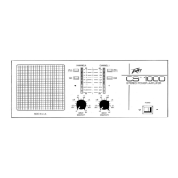
SENSITIVITY (9)
Controls the output signal level. Maximum output level is obtained by rotating this control fully clockwise.
UNBALANCED
1/4"
PHONE JACK INPUT (10)
Use to connect line level signal to the power amplifier .
UNBALANCED XLR INPUT (11)
Use to connect line level signal to power amplifier. The XLR is parallel with the
1J4'
input jack.
LINE CORD (120V products only) (12)
For your safety, we have incorporated a 3-wire line (mains) cable with proper grounding facilities. It is not advisable to
remove the ground pin under any circumstances. If it is necessary to use the equipment without proper grounding
facilities, suitable grounding adaptors should be used. Less noise and greatly reduced shock hazard exists when the unit
is operated with the proper grounded receptacles.
FUSE (13)
The fuse is located within the cap of the fuseholder. If the fuse should fail, IT MUST BE REPLACED WITH THE SAME
TYPE AND VALUE IN ORDER TO AVOID DAMAGE TO THE EQUIPMENT AND TO PREVENT VOIDING THE
WARRANTY. If the amp repeatedly blows fuses, it should be taken to a qualified service center for repair.
WARNING: THE FUSE SHOULD ONLY BE REPLACED WHEN THE POWER CORD HAS BEEN DISCONNECTED FROM
ITS POWER SOURCE.
GROUND SWITCH (14)
Three position rocker-type switch which, in most applications, should be operated in its center or zero position. There
may be some situations when audible hum and/or noise will come from the loudspeaker. If this situation arises, position
the ground switch to either positive or negative
(+
or -) or until the noise is minimized. NOTE: Should the noise problem
continue, consult your Authorized Peavey Dealer, the Peavey Factory, or a qualified service technician. THE GROUND
SWITCH IS NOT FUNCTIONAL ON 220/240 VOLT MODELS.
.
~
SPECIFICATIONS
RATED POWER
60W RMS into 16, 8, & 4 ohms, both
sides driven
(Continuous sine wave with less than
5% THO, 40 Hz to 20 kHz, 120V AC)
65W RMS into 16, 8,
&
4 ohms per
channel, one side driven
POWER @ CLIPPING (TYPICAL)
60W RMS into 16, 8,
&
4 ohms
(Continuous sine wave with less than
5% THO, 40 Hz to 20 kHz, 120V AC)
FREQUENCY RESPONSE
+0, -3 dB @ 50W RMS
into 16, 8, & 4 ohms, 40 Hz to 20 kHz
DAMPING FACTOR
Oesigned for 1 @ 16, 8, & 4 ohms
HUM & NOISE
85 dB below full rated power
(40 Hz to 20 kHz, unweighted)
FEATURES:
• Single-speed fan cooling system
• Single XLR & phone plug input per channel
• Transformer balanced XLR direct output
• Line output with adjustable level control
• Standby switch with LED indication
• Input attenuator control
INPUT
Input Impedance: 250K ohms
Minimum Input Level: 1V RMS, 0 dBV
DIRECT OUTPUT
Output Impedance: 270 ohms
Nominal Output Level:
0.3V RMS, -10 dBV
Transformer Balanced
LINE OUTPUT
Output Impedance: 10K ohms
Maximum Output Level:
23V RMS, 27 dBV
WEIGHT
&
DIMENSIONS
30 Lbs.
19"W
x
5v."Hx10"O
DANGER
EXPOSURE TO EXTREMELY HIGH NOISE LEVELS MAY CAUSE A PERMANENT HEARING lOSS_ INDIVIDUALS VARY CONSIDERABLY IN SUSCEPTIBILITY TO NOISE INDUCED HEARING LOSS, BUT NEARLY
EVERYONE WILL LOSE SOME HEAFiING IF EXPOSED TO SUFFICIENTLY INTENSE NOISE FOR A SUFFICIENT TIME
THE U,S, GOVERNMENT'S OCCUPATIONAL SAFETY AND HEALTH ADMINISTRATION (OSHA) HAS SPECIFIED THE FOLLOWING PERMISSIBLE NOISE LEVEL EXPOSURES
DURATIONPERDAY IN HOURS SOUND LEVELdBA, SLOW RESPONSE
8
9<J
92
95
97
100
102
105
110
4.. All operating instructions should be followed
5, This product should not be used near water. i.e. a
bathtub. sink, swimming pool. wet basement. etc
6. This product should be located so that its position does
not Interfere with Its proper ventilation, It should not be
placed flat against a wallar placed in ~ buill-in enclosure
that will Impede the flow of cooling air
7. This product should not be placed near a source of heat
such as a stove, radiator or another heat producing
amplifier
OF THE ABOVE PERMISSIBLE LIMiTS COULD RESULT IN SOME HEARING LOSS
. . r;~;';
:ID~Mt;
10. Power supply cords should always be handled carefully
Never walk or place equipment on power supply cords
Periodically check cords for cuts or signs of stress.
especially at the plug and the point where the cord exits
the unit
11 The power supply cord should be unplugged when the
unit is to be unused for long periods oftime
12, If this product is to be mounted in an equipment rack, rear
support should be provided
14. Care should be ,taken so that objects do not fall anc
liquids are not spilled into the unit through the ventilation
holes or any other openings
15. This unit should be checked by a qualified service
technician if
A. The power supply cord or plug has been damaged
B. Anything has fallen or been spilled Into the unit
C. The unit does not operate correctly.
D. The unit has been dropped orthe enclosure damaged
16, The user should not to attempt
10
service this equipment
All service work should be done by a qualified service
technician
 Loading...