Do you have a question about the Peavey CS 1000X and is the answer not in the manual?
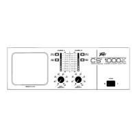
Details front panel LEDs, input sensitivity, and power switch.
Indicates when DDT compression is active or clipping occurs.
Indicates when a channel is operating above safe temperature limits.
Tri-colored LED arrays indicate output power levels for each channel.
31 detent controls for adjusting input sensitivity and gain.
Front panel rocker switch for turning the amplifier on and off.
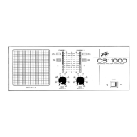
Covers grilles, switches, power source, and circuit breaker.
Rear panel opening for cooling air intake; must not be blocked.
Switch to enable or disable the DDT compression circuitry.
Connection requirements and protection against overcurrent.
Selects between stereo and bridge operating modes.
Describes various input, output, and crossover connectors.
XLR input jacks for balanced or unbalanced signals.
Sockets for optional line-balancing transformer modules (PL-2).
Ports for plug-in crossover modules and associated signal patching.
Parallel 1/4" jacks for direct signal input to the power amp.
Details connection options for loudspeakers.
Provides 1/4" jacks and 5-way binding posts for speaker connections.
Covers general, industrial, commercial, and rack-mount installation.
Recommendations for mounting and cooling in studio environments.
Details on connecting signals to and from the amplifier.
Instructions for powering on and setting initial levels.
Configuration for unbalanced input signals in stereo mode.
Configuration for balanced input signals using transformer modules.
Setting up the amplifier for biamplification with crossover modules.
Mono biamplification setup using one crossover module.
Operating the amplifier as a single, higher-power unit.
Guidance on setting input sensitivity for optimal performance and noise.
Explanation of the dynamic compression system for preventing clipping.
Details on heat dissipation, fan control, and thermal protection.
Information on thermal shutdown conditions and failure detection.
Explanation of passive crossovers and biamplification benefits.
Key considerations and best practices for biamplified systems.
Important operational details and warnings for bridge mode.
Guidance and warnings for qualified service personnel.
Precautions regarding disassembly and high voltage.
Visual guides for various connection and mode configurations.
Details on warranty coverage, exclusions, and claims.
General safety precautions for operating the amplifier.