12
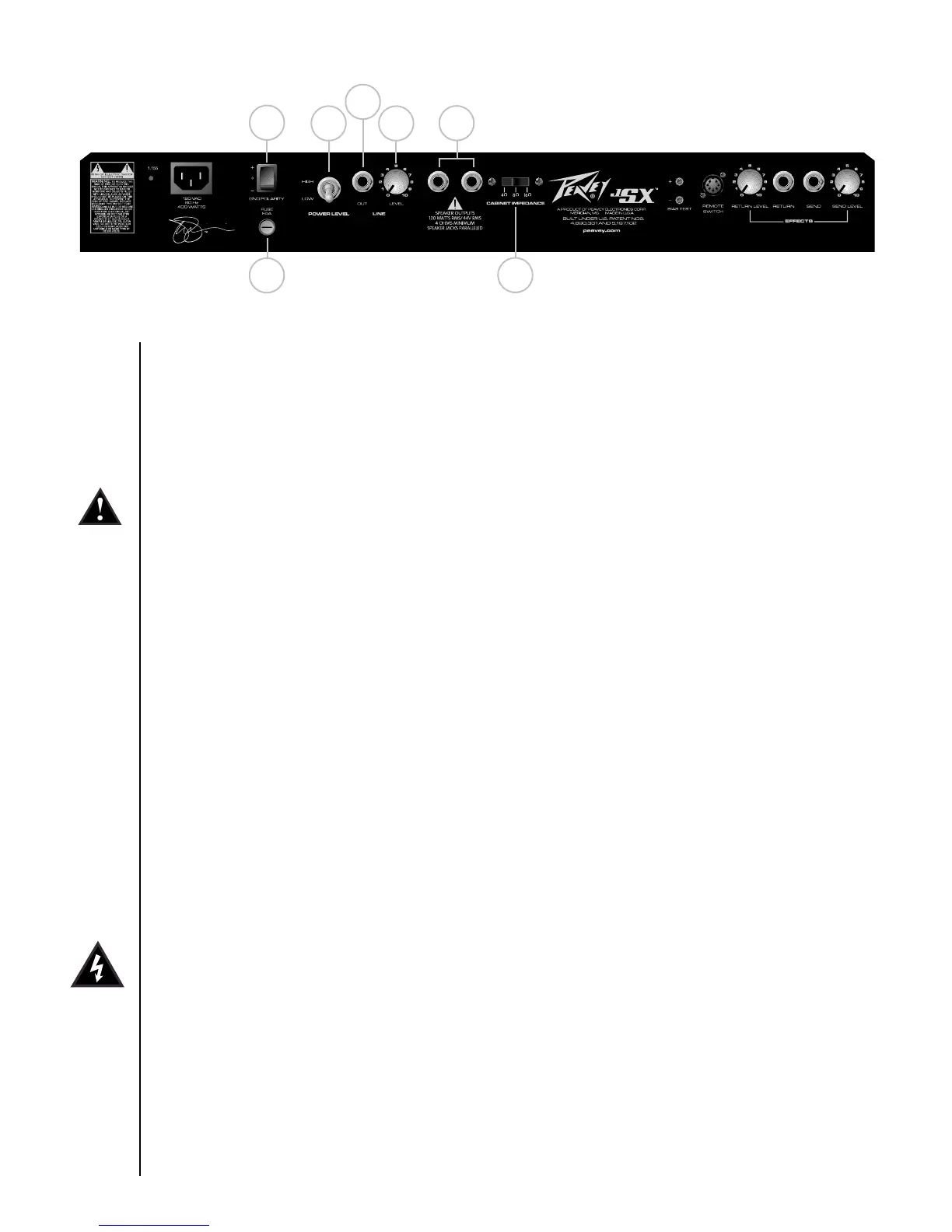
(28) CABINET IMPEDANCE SWITCH
This three-position switch allows appropriate selection of speaker cabinet impedance. If two
enclosures of equal impedance are used, the switch should be set to half the individual value. For
example, two 16 ohm enclosures necessitate an 8 ohm setting, while two 8 ohm enclosures would
require a 4 ohm setting. Minimum speaker impedance is 4 ohms.
(29) SPEAKER OUTPUTS
These paralleled 1/4" mono (TS) jacks are provided for the connection of speaker enclosure(s). Again,
minimum speaker impedance is 4 ohms. The CABINET IMPEDANCE SWITCH (28) should be set to
match the load of the speaker cabinet(s).
(30) LINE OUT LEVEL
This control sets the level of signal being sent out of the LINE OUT (31) jack. It may be used to balance
the level of slave power amp/speaker systems driven from the LINE OUT (31) to the level of cabinets
driven from the SPEAKER OUTPUTS (29).
(31) LINE OUT
This 1/4" mono (TS) jack provides a post-power amp signal to drive another power amp/speaker
system while maintaining the amplifier’s tone.
(32) HIGH/LOW POWER SWITCH
This switch allows the user to change the available output power of the amplifier from the standard
full power output rating (HIGH) to a lower power output (LOW) for venues that require lower volume
levels or for players who prefer high levels of distortion from the power amplifier section at lower
volumes.
(33) FUSE
A fuse is located within the cap of the fuse holder. This fuse must be replaced with one of the same
type and value to avoid damaging the amplifier and voiding the warranty. If the amp repeatedly blows
the fuse, it should be taken to a qualified service center for repair.
WARNING: THE FUSE SHOULD ONLY BE REPLACED AFTER THE POWER CORD HAS BEEN
DISCONNECTED.
(34) GROUND POLARITY SWITCH
This three-position, rocker-type switch should normally be placed in the center (0) position. If hum
or noise is noticed coming from the speaker enclosure(s), the switch may be placed in the “+” or “-”
position to minimize hum/noise. If changing the polarity does not alleviate the problem, consult your
authorized Peavey dealer, the Peavey factory or a qualified service technician.
33
28
29
30
31
32
34
 Loading...