Do you have a question about the Peavey Mark III Series and is the answer not in the manual?
| Brand | Peavey |
|---|---|
| Model | Mark III Series |
| Category | Musical Instrument Amplifier |
| Language | English |
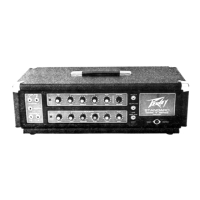
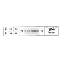
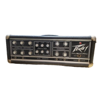
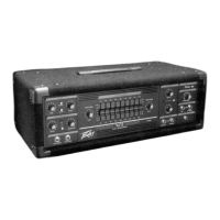
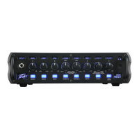
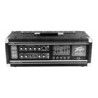
Overview of the Peavey Mark III Bass amp, highlighting its advanced circuitry and contemporary design.
Details the high and low gain inputs, their usage, and automatic gain balancing when both are used.
Explains the AUTOMIX function, its switching mechanism, and how it enables dual-channel operation.
Defines the pre gain control's function in determining input preamp sensitivity, not output power.
Details the passive equalization for Channel A, including low and middle frequency controls.
Explains the low equalization control's function and its potential for significant bass emphasis.
Describes the middle equalization control for tailoring mid-range frequencies and altering channel voicing.
Details the high equalization control, its boost effect, and potential issues with overboosting.
Covers Channel B's active equalization, including low, parametric middle, and high frequency controls.
Explains the active shelving low EQ control for boosting or cutting low frequencies.
Describes the PARAMID equalizer's dual function for varying center frequency and boost/cut amount.
Details the PARAMID control for boosting or cutting selected frequencies, with care for overboosting.
Explains the SHIFT control's function in determining the peak or notch center frequency.
Details the active shelving high EQ control for boosting or cutting high frequencies.
Explains the post gain controls as master volume for each channel, recommending settings for dynamics.
Describes the variable electronic crossover for bi-amping, allowing frequency setting between 50-500 Hz.
Details the graphic EQ assign switch for routing channels through or bypassing the graphic equalizer.
Explains the DDT compression, its purpose to prevent clipping, and the function of the limit LED and switch.
Details the six-band active graphic EQ, its frequency points, bandwidth, and 30 dB range for each band.
Covers the patch panel functions, including effects device patching and frequency-compensated low impedance output.
Explains the preamp out/power amp in jacks for inline patching of accessories and effects devices.
Describes the line output's speaker-system-matched frequency response, avoiding the need for direct boxes.
Details the Bi-Amp Low Out, the crossover network's low frequency output attenuated at 12 dB per octave.
Details the Bi-Amp High Out, the crossover network's high frequency output attenuated at 12 dB per octave.
Explains the purpose of bi-amping, using separate amps for low/high frequencies and variable crossover settings.
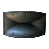
Advises against using high frequency horn/driver combinations with bass guitar systems for better sound.
Explains the pilot LED function, indicating when the amplifier is switched on and delivering power.
Details the DIN type socket for the remote footswitch, emphasizing proper plug insertion and care.
Instructs on fuse replacement, stressing the use of the proper type and value to prevent damage.
Explains the three-position power switch, its ON/OFF states, and selecting the position for minimal hum.
Emphasizes the importance of the three-wire line cord for safety and grounding, advising against removing the ground pin.
Details the parallel speaker output jacks, their compatibility with various impedances, and performance with 4-Ohm loads.
Warns against blocking the heatsink or cooling grille to ensure proper thermal dissipation and prevent overheating.
Describes the cord retainers on the rear panel for cable storage and unwrapping during operation.
Lists output power, sensitivity, input impedance, and signal-to-noise ratio for the bass amplifier.
Illustrates a bi-amp connection using the bass amp's speaker output and an external power amp.