EasyManua.ls Logo

Peavey PA 200 User Manual

Peavey PA 200
4 pages
To Next Page IconTo Next Page
Page #1 background imageLoading...
Page #1 background image
PA
200
MINER
ANMP
OWNERS
MANUAL
IR
PUT
REVERS
POWER
AMPLIFICATION
SECTION:
|
|
200
MODULE
Output
Power
@
1
kHz
@
117
VAC
Line:.
1.
Rated
Power:
100
W
RMS
@
Rated
Load:
4
Ohms
2.
`
Power
vs.
Distortion:
LOAD
IMPEDANCE
8
|
4
.
OHMS
OUTPUT
@
1%
THD
.
60
|
i
90
WwW
OUTPUT
@5%
THD
70
100-
Peak
Output
@
Rated
Load:
7
Amps
&
28
Volts,
200
Watts
Music
Power
Output
@
Rated
Load:
130
Watts
RMS
@
1%
THD
Frequency
Response:
3
dB
Down
@
50
Hz
&
15
kHz
Sensitivity
@
Rated
Power
&
Load:
300
my
Input
Impedance:
22
k
Ohms
PRE-AMPLIFIER
SECTION:
Input
Characteristics:
(Tone
Controls
Flat,
Volume
@
Maximum,
Master
@
12:00)
1.
Sensitivity:
4
mV
@
1
kHz
2.
Input
Impedance:
100
k
Ohms
Unbalanced
3.
Noise:
56
dB
(Open
Circuit),
60
dB
(50
k
Ohms),
66
dB
(Short
Circuit)
Distortion
@
1
kHz
@
Rated
Output:
Less
than
0.1%
THD
Frequency
Response:
3
dB
Down
@
40
Hz
&
20
kHz
Tone
Controls:
+
15
dB
@
50
Hz
&
10
kHz
Reverb/Effects
Send
Control:
Continuously
variable
each
channel
MASTER
SECTION:
Reverb
Return
Control:
Continuously
variable
with
footswitch
cut-off
Main/Monitor
Output
Level:
2.0
V
RMS
into
10k
Ohms
_
Effect
Output
Level:
1.0
V
RMS
into
10
k
Ohms
Question and Answer IconNeed help?

Do you have a question about the Peavey PA 200 and is the answer not in the manual?

Peavey PA 200 Specifications

General IconGeneral
BrandPeavey
ModelPA 200
CategoryAmplifier
LanguageEnglish

Summary

Power Amplification Specifications

Output Power Ratings

Details rated power, peak output, and music power output at specified loads and distortion levels.

Frequency Response and Sensitivity

Specifies frequency response range and input sensitivity for the power amplifier section.

Pre-Amplifier Section Specifications

Input Characteristics and Noise

Details input sensitivity, impedance, and noise levels for the pre-amplifier.

Distortion and Frequency Response

Specifies distortion levels and frequency response for the pre-amplifier.

Tone Controls and Effects Send

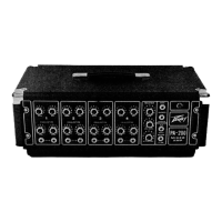
Describes tone control ranges and the reverb/effects send control functionality.

Master Section Controls

Reverb Return and Output Levels

Details the reverb return control and output levels for main/monitor and effects.

Channel Controls and Functions

Gain and Effects Send Controls

Explains the function of the gain control and the effects send control for each channel.

Low and High Equalization

Describes how the low and high equalization controls affect channel frequency response.

Input Jacks and Microphone Matching

Details the dual input jacks per channel and their function for microphone matching.

Master Section Operation

Master Gain Control

Explains the master gain control for overall system level and its recommended setting.

Auxiliary Level and Input

Describes the auxiliary input channel for additional mics or effects units.

Reverb Return Control

Details the reverb return control for blending the delayed signal into the mix.

Rear Panel Connections and Features

Auxiliary Input and Reverb Footswitch

Explains the auxiliary input jack and the reverb footswitch jack for external control.

Pilot Light, Power Cord, and Fuse

Describes the pilot light, importance of the 3-wire power cord, and fuse replacement.

Line Power Switch and Speaker Outputs

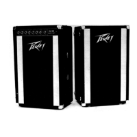
Details the line power switch positions and specifications for speaker output jacks.

Related product manuals