20
14.0 RELIEF VALVE
15.0
MAINTENANCE OF THE PROTECTION FILTER APPARATUS FOR PG-35 / PG-38 UNITS
The frequency of the cleaning of the protection filter depends on the type of product and the environment in which
the unit operates in. Under normal operating conditions the filter should be cleaned every 6 months.
The procedure is described below:
1) Loosen the bolts at the top to be able to remove the cover of the filter unit.
2) Ensure that there are no deposits which can fall into the
blower when extracting the filter.
3) Loosen the bolt at the top of the protection filter before extracting it.
4) After extracting the filter, it may be cleaned with compressed air. If the unit is
used in a greasy environment, we recommend using a solvent.
5) Mount the filter, keeping it free of foreign bodies.
6) Before starting the electric motor, turn the blower axis manually and check it turns
freely, to ensure the absence of foreign bodies.
when the blower is started u
ative effect of the overload resultin
counter-pressure at start-up as well as a
htened to block the system,
General
The PG unloading valve removes the air produced
when the blower is started up. This aliminates the
negative effect of the overload resulting from the
counter-pressure at start-up as weell as a gradual
start-up.
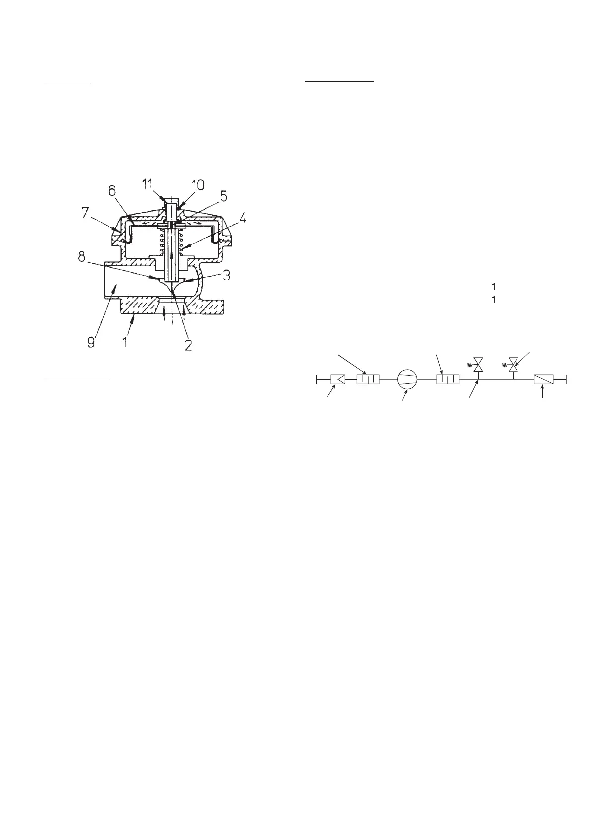
Installation
The relief valve should be installed between the thrust
silencer and the non-return valve as shown in the diagram.
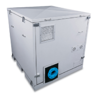
Functioning
When the blower is stopped, the valve is open.
Whwn the blower is started up, the air escapes through the
conduit (pos. 9) and at the same time passes throgh the
valve chamber. This produces dynamic pressure, which
acts on the top of the membrane (pos. 6) in such a way that
it is compressed downwards and closes the valve.
The valve reaction time is regulated by the bolt (pos. 11)
in such a way that the greater the dynamic pressure the
faster the valve is closed. Once the dynamic pressure has
been regulated, the nut (pos. 10) should be tightened to
block the system, avoiding any variation in the
aforementioned pressure.
 Loading...