Model 2745, Wireless Door Controller Installation and Operation Manual
The Peelle Company Guide 224
www.peelledoor.com Page 9 April 2011
VII. POWER AND MOTOR CONNECTIONS
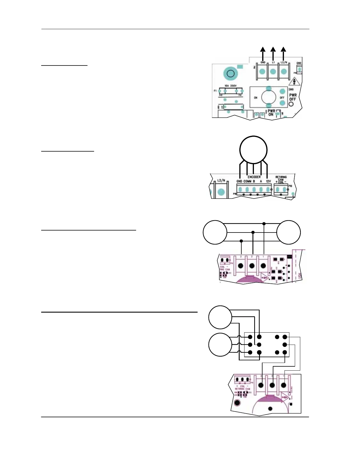
Power (FIG. 4)
Connect controllers in accordance with National Electrical
Code, Canadian Electrical Code, and other local codes
that apply. Power branch circuit should come from
machine room disconnect 10 amp circuit. Maximum 10
controllers per circuit. Use #14AWG copper wire for power
connection.
• ON/OFF switch disconnects both lines
• If neutral is not used, main disconnect must break
both lines.
Encoder (FIG. 5)
Install and wire encoder near the controller. Do not
extend the encoder wire. Encoder direction does not
matter; direction is established during the LEARN setup.
Connect the wires from the encoder directly to the
terminal blocks.
Landing Door Motors (FIG. 6)
Wire both door motors in parallel. Use #18AWG wire in
conduit for motor connection.
Do not combine motor wires with control wires in same
conduit.
Note: Peelle door motor low speed winding is not used.
Cap black wires separately (T4-T5).
Car Door (Gate) and Retiring Cam Motor (FIG. 7)
Car door motor and retiring cam motor are driven by the
same controller. A relay is provided in the controller to
switch between the car gate and retiring cam motor
operation. Use #18AWG wire in conduit for motor
connection.
Do not combine motor wires with control wires in same
conduit.
Note: Peelle car gate motor low speed winding is not
used. Cap black wires separately (T8-T9).
GND
L2/N
L1
208-240V AC
FIG. 4 – AC LINE CONNECTION
ENCODER
FIG. 5 – ENCODER CONNECTION
BROWN=12V
GREEN=A
YELLOW=B
WHITE=COMM
SHIELD=GND
T1
T2
T3
DOOR
MOTOR
DOOR
MOTOR
FIG. 6 – DOOR MOTOR CONNECTION
FIG. 7 – CAR GATE AND RETIRING
CAM MOTOR CONNECTION
GATE
MOTOR
RET.
CAM
MOTOR
RELAY


 To Next Page