10. Circulator: The boiler circulator is to be sized to
overcome the pressure drop of the system while
providing the flow required by the boiler.
a. If the boiler is piped in a secondary loop of a
primary/secondary heating system, the circulator
will need only to overcome the resistance of the
boiler and any fittings in that loop.
b. The circulator should be sized based on gross
output of the boiler. Table 4.3 shows the Boiler
Output as reported to the Hydronics Institute
Section of AHRI.
c. The required flow is calculated based on the design
temperature difference from the return to the supply
of the boiler. For a PF-110 with a design temperature
difference of 20°F the calculation is as follows.
Output 101,000
Required Flow =
________
=
_________
= 10.1 GPM
Δ
T x 500 20 x 500
19
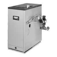
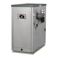
WATER PIPING AND CONTROLS
PUREFIRE
®
Model
Boiler Input
Btu/hr (kW)
Gross Output
Btu/hr (kW)
PF-50 50,000 (14.7) 46,000 (13.5)
PF-80 80,000 (23.4) 74,000 (21.7)
PF-110 110,000 (34.2) 102,000 (29.9)
PF-140 140,000 (41.0) 131,000 (38.4)
PF-200 199,000 (58.3) 183,000 (53.6)
PF-210 210,000 (61.5) 193,000 (56.6)
PF-300 300,000 (87.9) 289,000 (84.9)
PF-399 399,000 (116.9) 373,000 (109.3)
Table 4.3: Boiler Inputs and Outputs
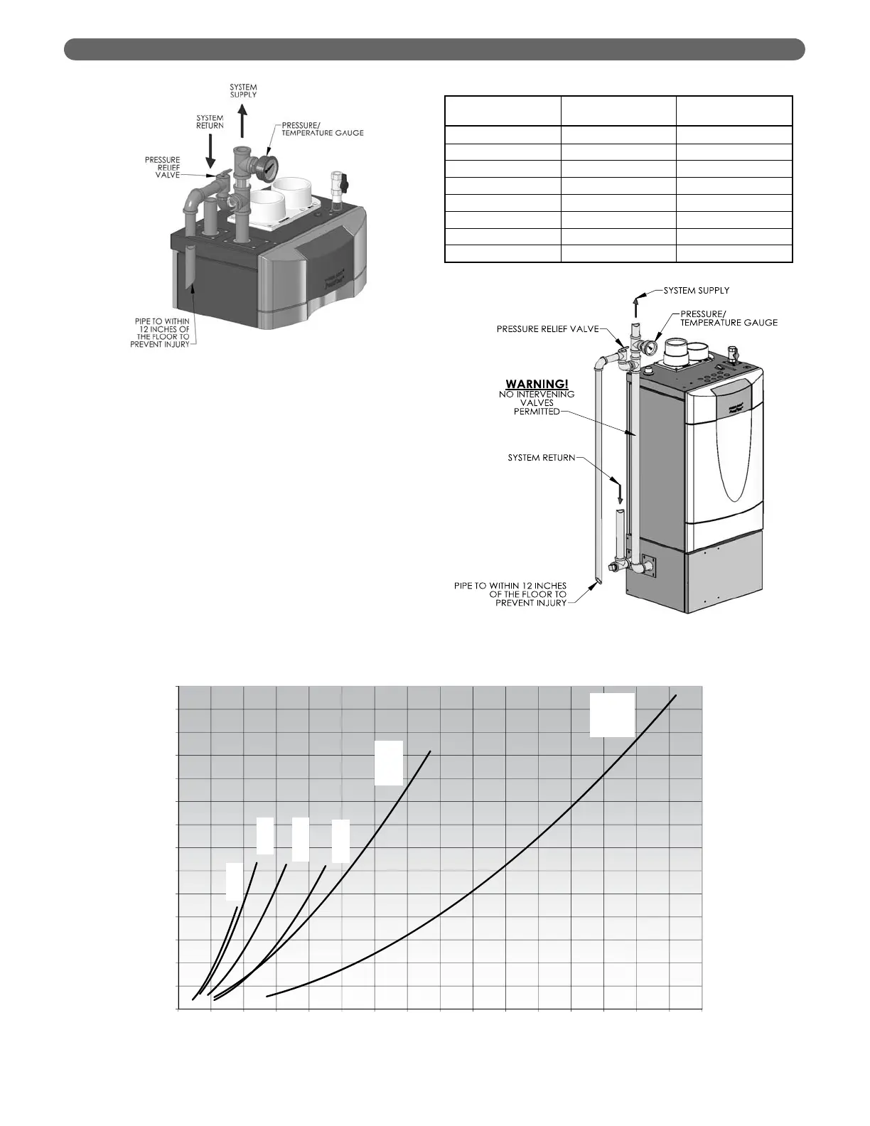
Figure 4.4: PUREFIRE
®
Circulator Sizing Graph (General Pump – Primary/Secondary)