34
ELECTRICAL CONNECTIONS
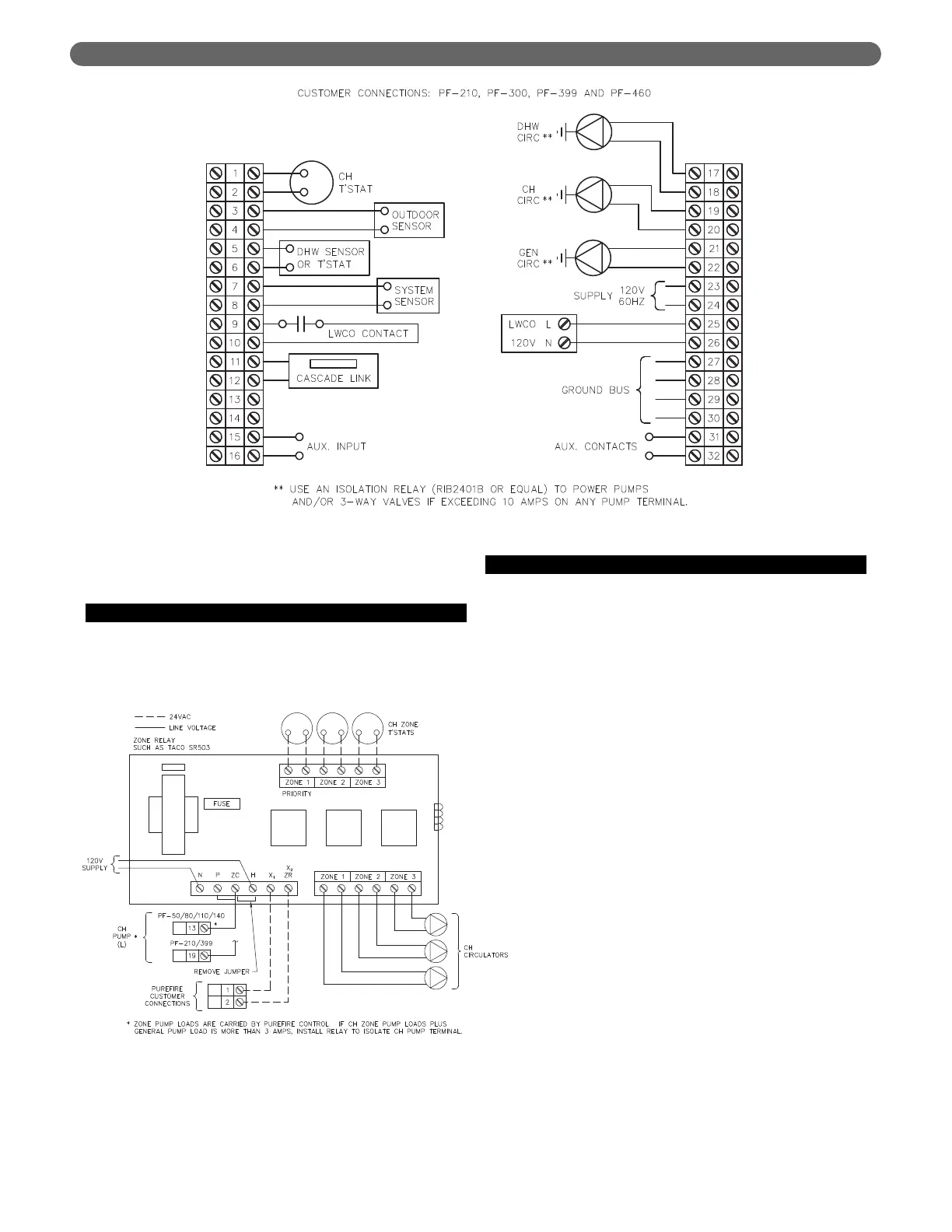
Figure 7.3: Customer Connections – PF-200, PF-210, PF-300 and PF-399
5. Note that the service switch does not disconnect
power to the convenience outlet.
C. ZONE CIRCULATOR WIRING
Wiring for a typical circulator zone relay is shown in
Figure 7.4.
D. INTERNAL WIRING
Figure 7.5 shows the complete boiler wiring schematic for
PF-50, PF-80, PF-110 and PF-140 boilers. Figure 7.6
shows the schematic wiring diagram for the PF-200,
PF-210, PF-300 and PF-399 boilers. The following is a list
of internal wiring components.
1. User Interface: The user interface is attached to the
front of the electrical junction box and is accessible by
removing the tinted lens on the front of the boiler.
This interface allows users and installers to
communicate with the control.
2. Supply/Return Sensors: These component, located on
the left header are a pair thermistors that provide
supply and return water temperature information to
the control. Be sure to use only a P
UREFIRE
®
supply
thermistors for this boiler.
3. Limit Switch: This component is a bi-metal switch that
will prevent the boiler from reaching temperatures
above 203°F (95°C) to prevent damage to the boiler.
Be sure to use only a P
UREFIRE
®
supplied switch
4. Flue Sensor: This thermistor provides flue temperature
information to the control. It is located in the back of
the electrical junction box behind the user interface.
5. Condensate Drain Float Switch: This switch is
mounted in the condensate collector below the heat
exchanger in the rear of the cabinet.
6. Service Switch: The service switch interrupts the
power to the P
UREFIRE
®
boiler to allow service to be
performed.
Figure 7.4: Typical Zone Circulator Relay Wiring