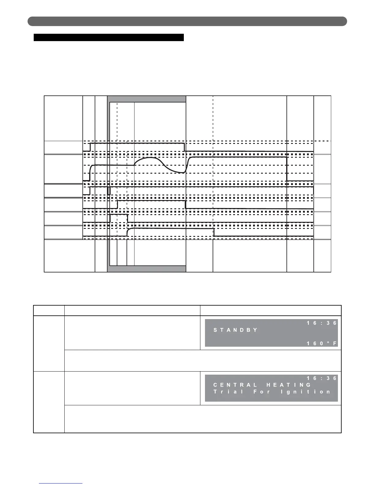
B. IGNITION SEQUENCE
Figure 8.1 shows the ignition sequence for the PUREFIRE
®
boiler control. Table 8.3 describes each step in the
sequence in detail. The P
UREFIRE
®
boiler control provides
dual sensing of the flame to maximize the reliability. The
control senses the burner flame with both the flame
sensor and the ignition electrode.
40
BOILER CONTROL: INTERNAL WIRING & OPERATION
Figure 8.1: Ignition Cycle – Graphical Representation
Table 8.4: Ignition Sequence
Period Demand Status User Interface Display
Standby
No demand is present
If the power is on to the PUREFIRE
®
boiler and there is no heat demand, the user interface will display “Standby” and show the
boiler supply temperature in the lower right corner. The time, in 24 hour format, is shown in the upper right. When a heat demand
(either CH or DHW) is present, the boiler begins the ignition cycle.
Pre Purge
A CH or DWH demand must be present to initiate ignition.
Once initiated the boiler will light.
When a demand is present, the PUREFIRE
®
control starts the combustion air fan. The fan speed then increases to ignition speed
and the user interface displays the Source of the call for heat along with “Trial for ignition.” This screen is displayed until the
burner is lit and stable or until a fault occurs. Once the ignition sequence begins it will continue through ignition even if the
demand has ended.