6 of 14
ISSUED: 01-10-07 SHEET #: 009-9039-2 03-12-07
3
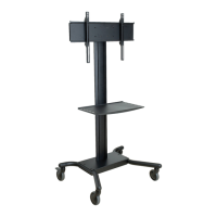
Insert and screw casters (U & T) into holes of support legs (S & R). Attach casters with brake (U) to the back of left and right support legs.
Attach casters without brake (T) to front of support legs as shown.
NOTE: Lock brakes on casters to avoid sudden movements during installation.
R
U
T
S
HAND THREAD
HOLD WHEEL
4
L
D
G
X
fig 4.2
CHORD MANAGEMENT
HOLES
fig 4.1
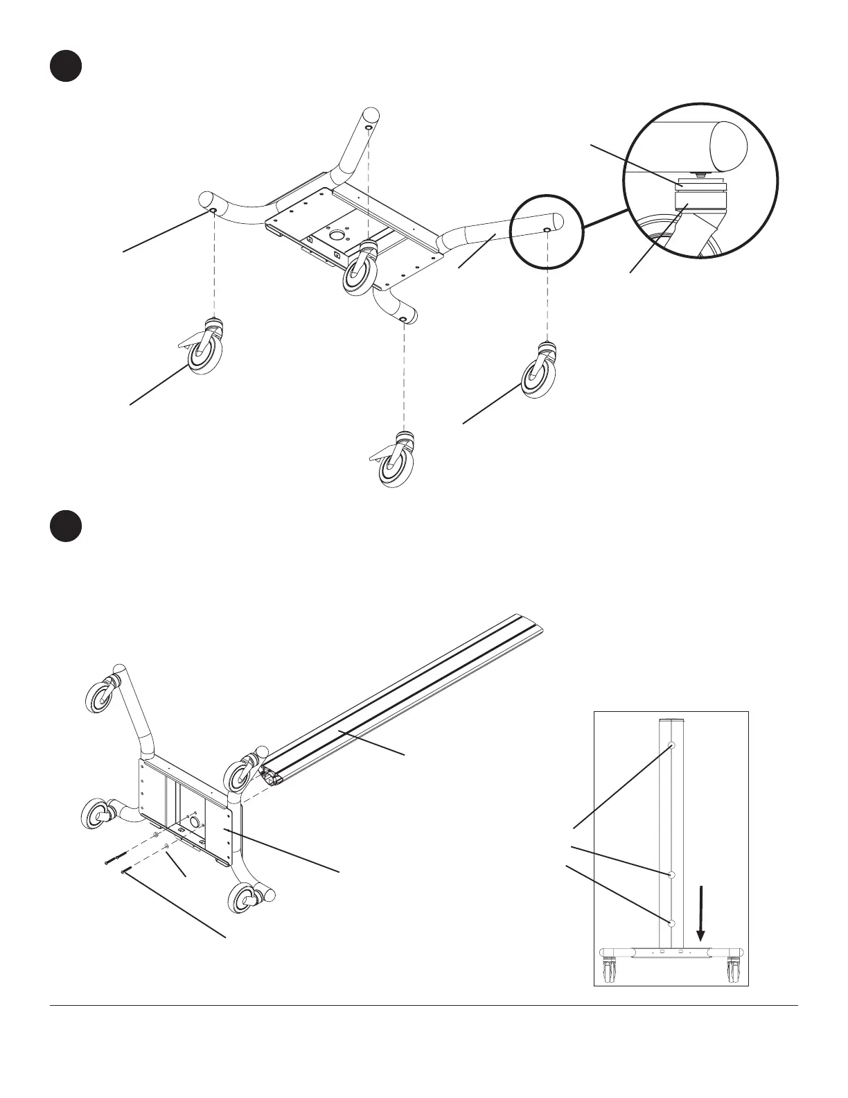
Attach upright (G) to base (D), as shown in in fig 4.2 using three 3/8-16 x 2.5" socket screws (L) and M10 x .402ID
lock washers (X). Tighten screws using 7/32" allen wrench (M) shown in fig. 4.1.