A421 Series Standard Electronic Temperature Controls Installation Instructions
5
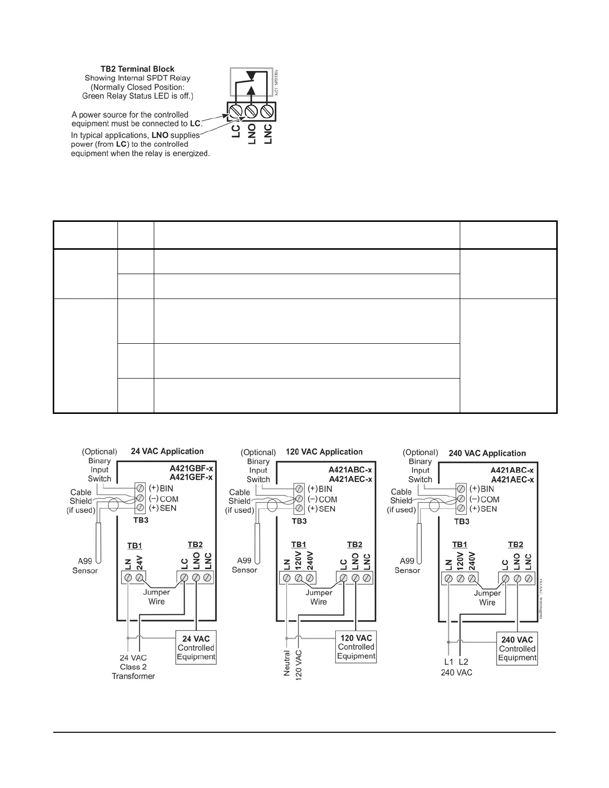
You can also provide an independent power source for
the A421 control on the TB1 terminals and then wire
the TB2 relay terminals to a separate power source for
switching and powering the controlled equipment
circuit.
Figure 3: TB2 Terminal Block Showing
Connections to the Internal SPDT Relay
Figure 4: Wiring the A421 Series Controls Using the Same Power Source
to Power the Control Operation and Power the Controlled Equipment
Table 2: A421 Control Wiring Terminals and Wire Size Information
Terminal
Block
Label Description, Function, and Requirements Recommended
Wire Sizes
TB1
24 VAC
Models
LN Low-Voltage 24 VAC Control Power (Common): Connect the 24 VAC
supply power to operate the control.
28 AWG to 12 AWG
0.08 mm
2
to 4.0 mm
2
24V Low-Voltage 24 VAC Control Power (Hot): Connect 24 VAC supply
power to operate the control (via jumper from LC in Figure 4).
TB1
120/240 VAC
Models
LN Line-Voltage Power Source (Common): Connect the neutral wire for 120
VAC supply power applications.
Connect the L1 supply power lead for all 208/240 VAC supply power
applications.
28 AWG to 12 AWG
0.08 mm
2
to 4.0 mm
2
120V Line-Voltage 120 VAC Control Power (Hot): Connect the 120 VAC supply
power (hot) for 120 VAC supply power applications (via jumper from LC in
Figure 4).
240V Line-Voltage 240 VAC Control Power (L2) Terminal: Connect the L2
supply power connection for 208/240 VAC supply power applications (via
jumper from LC in Figure 4).