P266 Series Single-Phase Condenser Fan Speed Controls Installation Instructions 9
Setting Values and Modes
To change settings and values on a P266 Series
Control:
1. Determine the operating pressure setpoints (psig
or bar), voltage inputs and outputs (VAC), and the
other modes of operation required for your
condenser fan motor control application.
2. Convert the selected pressure setpoints (psig or
bar) and voltage targets (VAC) into P266 Series
Control values. See P266 Series Control Values
and Modes and Table 2.
3. Position the DIP switches to set the new values
and/or modes. See Setting Up the DIP Switch
Block.
4. Press and hold the push button until the number of
LED flashes indicates the desired value or set of
values and/or mode settings. Release the push
button after:
• two flashes to save the low pressure mode
setting and the start voltage value
• three flashes to save the start pressure value
• four flashes to save the end pressure value
• five flashes to save the split winding, end
voltage, low-speed capacitor mode, and
auxiliary fan stages mode settings
• six flashes to save the auxiliary fan overlap
value
• seven flashes to save the changeover voltage
value
Note: See Table 2 for more information about the
values and modes that are associated with the number
of LED flashes.
5. Repeat Steps 3 and 4 for the next value and/or
mode you need to change.
6. After you save all of the new values and mode
settings, set all of the DIP switches to the on
position to lock out the push button operation.
Setting Up the DIP Switch Block
To set new values and modes on the DIP switch block:
1. Position all of the switches on the DIP switch block
to the off position.
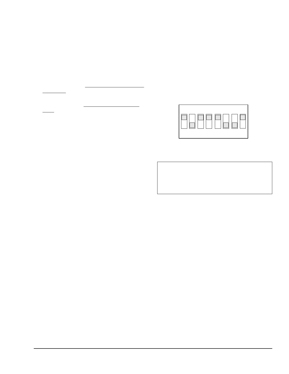
2. Position the numbered switches to on so that the
total of the switch numbers (in the on position)
equals the desired setup value. Start with the
highest number switch that is less than the setup
value. (For example, if the desired setup value is
185, position switch 128 to on first. Then position
switch 32 on, followed by switch 16, switch 8, and
switch 1 [128+32+16+8+1=185] [Figure 8]).
Mode settings require you to position only one or
two switches on the DIP switch block, depending
on the mode. See Table 2 for more information
about the values and modes that are associated
with the number of LED flashes.
Test Voltage Mode
Test voltage mode is a setup and diagnostic tool in the
P266 Series Control firmware that allows you to test
the operation of a condenser fan motor at different
voltage values in the field, and determine the optimal
start voltage value for your P266 Series Control
application.
Test voltage mode also allows you to determine and
set the optimal changeover voltage value for the
M3 triac in P266 Series Control applications that use a
low-speed capacitor.
To use the test voltage mode, you need:
• a P266 Series Control model designed for your
condenser fan application
• access to the condenser (and fan motor) controlled
by your P266 Series Control
• a clamp-on ampere meter with 15 A range (to
check changeover current draw when determining
changeover voltage value)
• an insulated probe to hold down the push button
and change the DIP switch positions
IMPORTANT: All of the switches on the DIP switch
block must be set to the proper positions for your
application before you press and release the push
button to save the values and/or mode settings. See
Table 2 for more information on switch positions.
Figure 8: A DIP Switch Block with the
Switches Positioned for a Setup Value of 185
128
64
32
16
8
4
2
1
 Loading...


