P266 Series Single-Phase Condenser Fan Speed Controls Installation Instructions8
Low-Speed Capacitor Mode
In some fan speed applications, a (user-supplied)
low-speed capacitor can be connected to the
P266 Series Control M3 triac and the controlled fan
motor (Figure 3 and Figure 4). The low-speed capacitor
is enabled at low voltages to enhance the fan motor
efficiency and performance. Set the low-speed
capacitor mode to on when a low-speed capacitor is
used.
Note: The optional low-speed capacitor should be
equal in both the voltage range and the microfarad
value to the auxiliary capacitor supplied by the
manufacturer, but the capacitor must not exceed
15 microfarads.
Note: You must also set the changeover voltage
value when a low-speed capacitor is used in your
P266 Series Control application. See Changeover
Voltage Value and Determining the Changeover
Voltage Value for more information on setting the
changeover voltage value.
Auxiliary Fan Stage Mode
You can set the P266 Series Control to cycle (on/off)
up to three additional (fixed-speed) fan motors or fan
stages in conjunction with the variable speed fan
controlled by the P266 Series Control.
Three low voltage circuits (Figure 2) can be wired to
control the auxiliary fan motor/stage starters. See
Table 2 for information on setting the number of
auxiliary fans used in your application.
Figure 7 shows a P266 Series Control application with
one auxiliary fan operating in conjunction with the
speed-controlled fan. When the condenser load
exceeds the output capacity of the speed-controlled
fan, the P266 Series Control powers on the auxiliary
fan and shifts the speed-controlled (P266) fan to a new
start pressure.
Auxiliary Fan Overlap Value
Auxiliary fan overlap value determines the pressure
range overlap (as a percentage of the total pressure
[throttling] range) between the fan stages set up on the
P266 Series Control. The fan overlap value is equal for
all auxiliary fan stages set up on the control.
Increasing the auxiliary fan overlap value decreases
the (on/off) cycling rate of the auxiliary fans, and
increases the pressure differential between auxiliary
fan stages (which increases the pressure range of
each auxiliary fan stage).
Note: If the P266 Series Control is set for no auxiliary
fans, the auxiliary fan overlap value is not used. See
Table 2 for information on setting the number of
auxiliary fans used in your application.
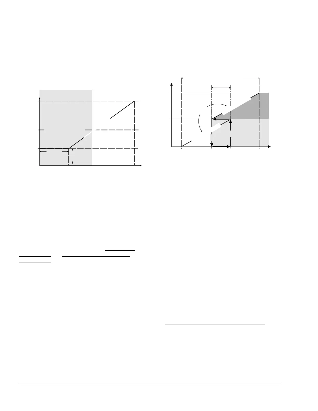
Changeover Voltage Value
The changeover voltage value determines the voltage
at which the P266 Series Control enables and disables
the M3 triac and the low-speed capacitor (Figure 6).
See Determining the Changeover Voltage Value
.
Figure 6: Low-Speed Capacitor Operation
Start
Pressure
0
Start
Voltage
End
Voltage
LPM
Off
Voltage to Motor
Pressure at Sensor
Low-Speed Capacitor
Enabled
Low-Speed Capacitor
V
o
l
t
a
g
e
t
o
M
o
t
o
r
266_CV_Rels
Figure 7: Speed-Controlled (P266) Fan Operating
with One Auxiliary (On/Off) Fan Stage
over the Entire Pressure Range
Start
Pressure at Sensor
Total
1st
Stage
P
2
6
6
F
a
n
O
u
t
p
u
t
Auxiliary
Aux.Fan
P266 Fan
P
2
6
6
F
a
n
O
u
t
p
u
t
Output Capacity
On
Off
Fan Throttling Range
 Loading...


