P266 Series Single-Phase Condenser Fan Speed Controls Installation Instructions4
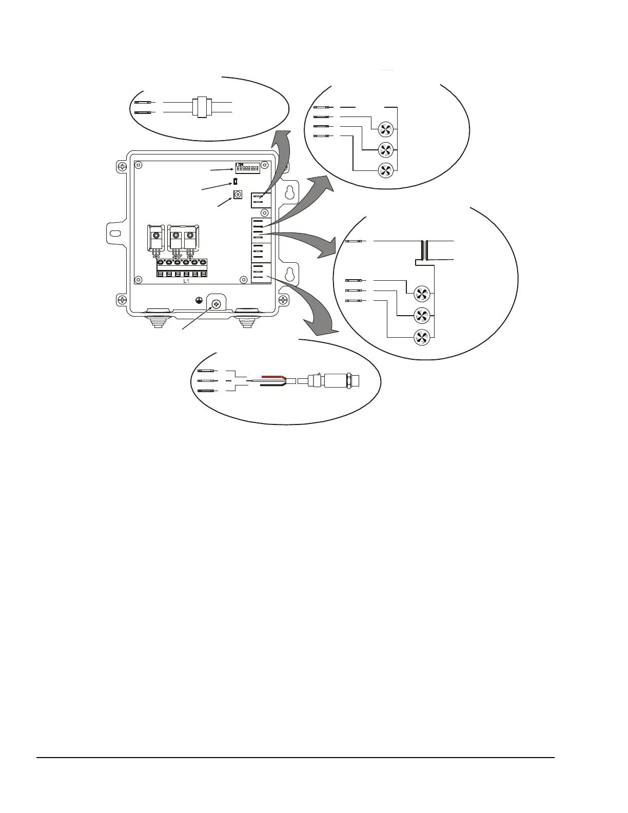
Figure 2: P266 Series Control Physical Features and Low Voltage Wiring
24 VAC Class 2 Supply Power Wiring
for , , and Type Controls
P266A P266B P266C
24 VAC Class 2
Power Supply
120/240 VAC
Primary Supply
Power
A
C
Fan 2 Starter
Fan 3 Starter
Fan 1 Starter
1
2
3
F
24 VAC Class 2 Fan Control Wiring
for , , and Type Controls
P266A P266B P266C
24 VAC
V
P
C
P1
P266 Electronic
Pressure Transducer
If a second P266 transducer is used,
wire the P2 terminals the same
as P1 terminals.
Pressure Transducer Class 2
Wiring for Models
All P266
Wht
Red
Blk
DIP Switch Block
Earth Ground
Connection
Push-Button
LED
M3
M2 M1
L2/N L2/N
A
C
A
1
2
3
F
V
P
C
V
P
C
P2
P1
Line-Voltage VAC
Fan 2 Starter
Fan 3 Starter
Fan 1 Starter
Low-Voltage (<30V)
Low-Voltage (<30 V) Class 2 Auxiliary Fan Control
Wiring for Type Controls
P266E
C
1
2
3
F
External Low-Voltage SELV
Power Supply
FIG:P266_lwV_wirng
 Loading...