System 450™ Series Control Modules with Analog Outputs Installation Instructions
11
2. Refer to the System 450 Series Modular Controls Product Bulletin (LIT-12011458), Catalog Page (LIT-1900549), or the
System 450 Series Controls Systems Technical Bulletin (LIT-12011459) for additional ordering information for System 450
compatible sensors and transducers.
3. See Setting Up Outputs That Reference a P110 Sensor
on page 12 for information on setting up System 450 outputs that
reference the P110 Sensor Type.
4. Many of the temperature sensors that can be set up as HI°F or HI°C Sensor Types are not designed for use across the
entire range of usable values for HI°F and HI°C Sensor Types. Refer to the Technical Specifications for the sensor you
intend to use to determine the ambient temperature range that the sensor is specified to operate in. The TE-6000-6 Nickel
Sensor is the only sensor designed for use over the entire temperature range.
5. Selecting the bin Sensor Type for a sensor (Sn-1, Sn-2, or Sn-3) sets up the input to control relay outputs (only) based on
the state of the binary input contacts (open or closed) connected to the sensor input (Sn1, Sn2, or Sn3). See Binary Input
Control for Relay Outputs on page 13 for more information. Can only be used for relay outputs.
Table 5: System 450 Sensor Setup Screen Information and Procedures (Part 1 of 2)
LCD Screen Name, Description/Function, User Action, and Example
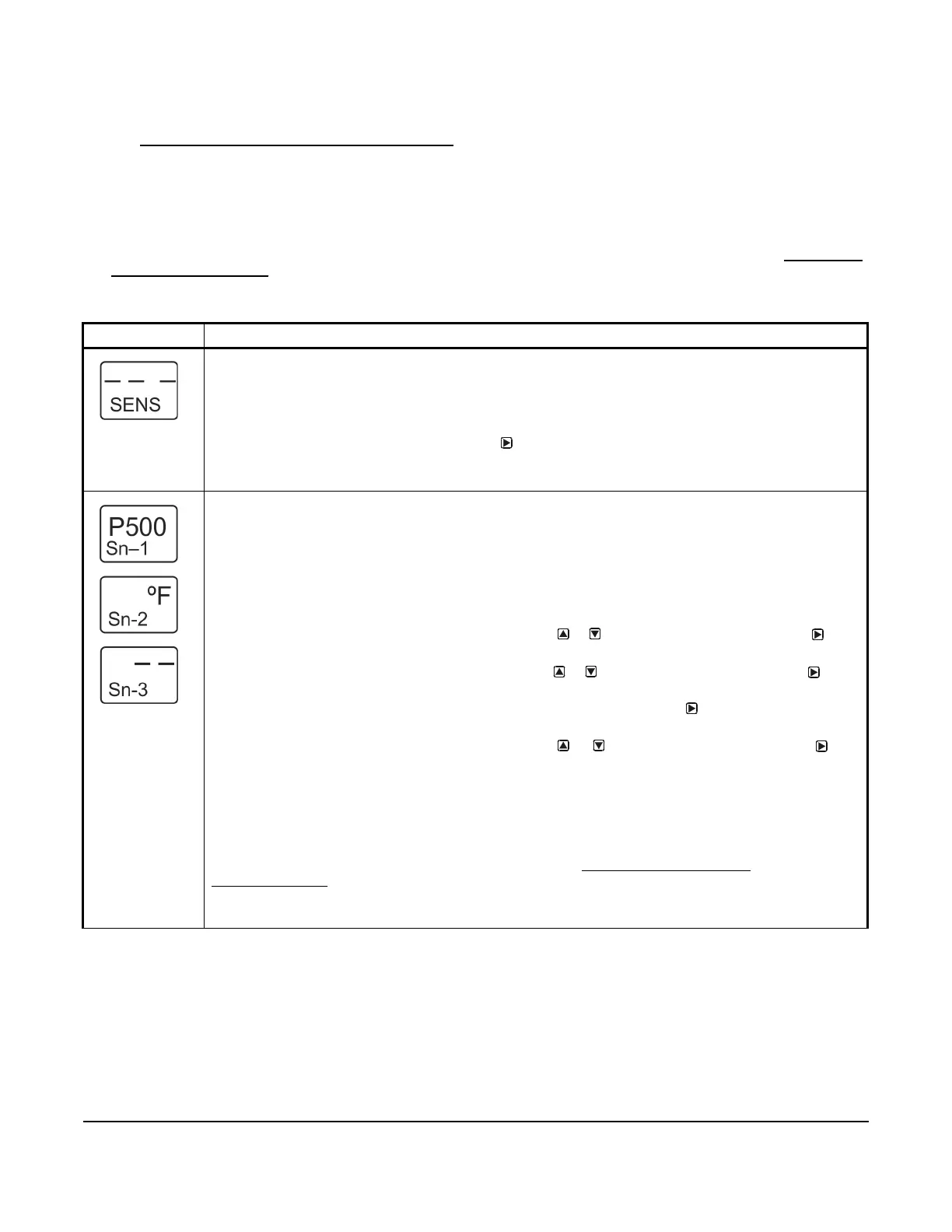
Sensor Setup Start Screen: The Sensor Setup Start screen is the first screen that is displayed when you
access the System 450 setup screens. From the Sensor Setup Start screen, you can navigate to the
Output Setup Start screens or the Sensor Setup screens. See Figure 6.
Note: You must set up the input sensors before you can set up the control system outputs. The Sensor
Setup Start screen is view-only; selections are not made in Setup Start screens.
1. In the Sensor Setup Start screen, press
to go to the first Sensor Type Selection screen
(Sn-1) and begin setting up the sensors in your control system.
The screen example shows the Sensors Setup Start screen with flashing dashes.
Sensor Type Selection Screens: The Sensor Type that you select for an input sensor automatically
determines the setup parameters and values for each output that is set up to reference that sensor. See
Table 4 for information about System 450 sensors/transducers, Sensor Types, condition type, units of
measurement, minimum control band or proportional band, setup values, value ranges, and product code
numbers.
Note: For outputs to operate properly, the selected Sensor Type must match the sensor/transducer
model wired to the control module, and the sensor/transducer must be wired to the proper control module
input terminals.
2. In the Sn-1 Sensor Type Selection screen, press or to select a Sensor Type. Press
to
save your selection and go to the Sn-2 Sensor Type Selection screen.
3. In the Sn-2 Sensor Type Selection screen, press or to select a Sensor Type. Press to
save your selection and go to the Sn-3 Sensor Type Selection screen.
Note: If your control system does not use three input sensors, simply press while the two dashes are
flashing in a Sensor Type Selection screen to save no Sn-3 Sensor Type and go to the next setup screen.
4. In the Sn-3 Sensor Type Selection screen, press or to select a Sensor Type. Press
to
save your selection and either:
• go to the Temperature Offset Setup screen for the first temperature sensor in your system.
• return to the Sensor Setup Start Screen, if your control system has no temperature sensors.
Note: Beginning with firmware Version 2.00, if you select the same Sensor Type for Sn-1 and Sn-2, two
additional functional sensors (Sn-d and HI-2) are available for selection when you set up the control
system outputs. If you select the same Sensor Type for Sn-1, Sn-2, and Sn-3, then functional sensor HI-3
is also available for selection when you set up outputs. See High Input-Signal Selection
on page 13 and
Differential Control
on page 14 for more information.
The screen examples show Sn-1 with the P500 Sensor Type selected, Sn-2 with the °F Sensor Type
selected, and Sn-3 with the no Sensor Type selected.
 Loading...

