*See Page 3
A COMPLETE LINE OF MOTOR DRIVES
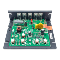
KBIC
®
Solid State SCR
DC Motor Speed
Controls
See table 2 page 4 for KBIC
®
models covered by this manual
Patented Ultra Fast
CL Circuit Prevents
Demagnetization in
PM Motors
Installation and
Operating
Instructions
See SAFETY WARNING on page 4
Basic KBIC
®
PATENTED
©1996 KB ELECTRONICS, INC.
™
TABLE OF CONTENTS
Section Page
i. Safety Warning ............................................................................ 3
ii. Simplified Instructions ........................................................................ 3
iii. Introduction ............................................................................... 6
I. Application Information ...................................................................... 6
II. Installation Instructions ...................................................................... 7
III. Adjustments & Control Functions ............................................................. 10
IV. Switching Circuits ......................................................................... 11
V. Limited Warranty .......................................................................... 16
TABLES
1. Nominal Trimpot Settings .................................................................... 3
2. Electrical Ratings ........................................................................... 4
3. General Performance Specifications ........................................................... 4
4. Fuse Selection Chart ....................................................................... 5
5. Plug-in Horsepower Resistor
®
Chart ........................................................... 5
6. Minimum Supply Wire Requirements ........................................................... 8
7. Field Connections .......................................................................... 8
8. Parts List ................................................................................ 15
FIGURES
1. Basic KBIC
®
.............................................................................. 5
2. Mechanical Specifications ................................................................... 7
3. Connection Diagrams ....................................................................... 8
4. ACCEL Trimpot Adjustment ................................................................. 10
5a. Master/Slave Circuit ....................................................................... 12
5b. Dynamic Brake Circuit ..................................................................... 13
5c. Overload Protection ....................................................................... 13
6. Schematic ............................................................................... 14
2