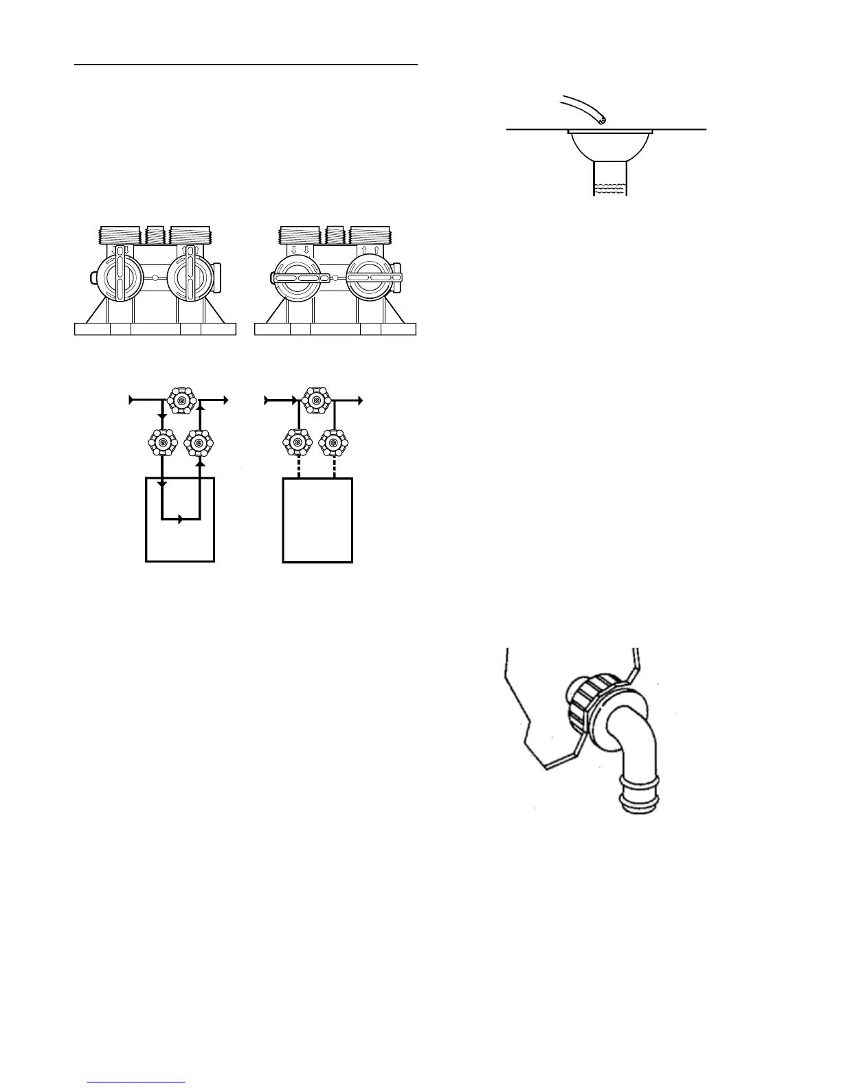
Water Line Connection
The installation of a bypass valve system is recommended to
provide for occasions when the water conditioner must be
bypassed for hard water or for servicing.
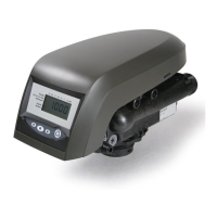
The most common bypass systems are the Autotrol
®
Series
256 bypass valve (Figure 4) and plumbed-in globe valves
(Figure 5). Though both are similar in function, the 256
Autotrol bypass offers simplicity and ease of operation.
B
Y
P
A
S
S
B
Y
P
A
S
S
Not in Bypass
B
Y
P
A
S
S
B
Y
P
A
S
S
In Bypass
Figure 4 Autotrol Series 256 Bypass Valve
Water
Conditioner
Water
Conditioner
Not in Bypass
In Bypass
Figure 5 Typical Globe Valve Bypass System
Drain Line Connection
1. Ideally located, the unit will be above and not more than
20 feet (6.1 m) from the drain. For such installations, use
an appropriate adapter fitting (not supplied), to connect
1/2 inch (1.3 cm) plastic tubing to the drain line connection
of the control valve.
2. If the unit is located more than 20 feet (6.1 m) from drain,
use 3/4 inch (1.9 cm) tubing for runs up to 40 feet (12.2 m).
Also, purchase appropriate fitting to connect the 3/4 inch
tubing to the 1/2 inch NPT drain connection.
3. If the unit is located where the drain line must be elevated,
you may elevate the line up to 6 feet (1.8 m) providing the
run does not exceed 15 feet (4.6 m) and water pressure
at conditioner is not less than 40 psi (2.76 bar). You may
elevate an additional 2 feet (61 cm) for each additional
10 psi (0.69 bar).
4. Where the drain line is elevated but empties into a drain
below the level of the control valve, form a 7-inch (18 cm)
loop at the far end of the line so that the bottom of the loop
is level with the drain line connection. This will provide an
adequate siphon trap.
5. Where the drain empties into an overhead sewer line, a
sink-type trap must be used.
IMPORTANT: Never insert drain line into a drain, sewer line or
trap. Always allow an air gap between the drain line and the
wastewater to prevent the possibility of sewage being back-
siphoned into conditioner.
Right Way
Drain Line Tube
Drain
Correct Way
Figure 6
NOTE: Standard commercial practices have been expressed
here. Local codes may require changes to
these suggestions.
Brine Line Connection
It will be necessary to install the brine tube and line to a fitting
installed on the air check. Apply plumber tape on all
threaded connections.
Be sure all fittings and connections are tight so that premature
checking does not take place. Premature checking is when
the ball in the air check falls to the bottom before all brine
is drawn out of the brine tank. See Placing Conditioner into
Operation section.
Overflow Line Connection
In the absence of a safety overflow and in the event of
a malfunction, the BRINE TANK OVERFLOW will direct
“overflow” to the drain instead of spilling on the floor where it
could cause considerable damage. This fitting should be on the
side of the cabinet or brine tank.
To connect overflow, locate hole on side of brine tank. Insert
overflow fitting (not supplied) into tank and tighten with plastic
thumb nut and gasket as shown (Figure 7). Attach length of
1/2 inch (1.3 cm) I.D. tubing (not supplied) to fitting and run to
drain. Do not elevate overflow line higher than 3 inches
(7.6 cm) below bottom of overflow fitting. Do not tie into drain
line of control unit. Overflow line must be a direct, separate
line from overflow fitting to drain, sewer or tub. Allow an air
gap as per drain line instructions (Figure 6).
Brine Tank
Overflow Fitting
Installed
Connect 1/2-inch
(1.3 cm) Tubing or
Hose and Run to
Drain
Figure 7
Low Voltage Transformer
Use only the included transformer for powering the 400 series
timers. Connect the plug of the transformer secondary cable
to the mating socket on the control (see Figure 8).
Be certain that the transformer is plugged into a correct
voltage source that is not controlled by a wall switch.
EQUIPMENT INSTALLATION continued
AUTOTROL
®
255 Valve/400 Series Service Manual • 5
 Loading...