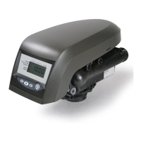
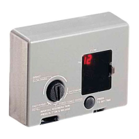
460TC Control
460TC
DAYS
CLOCK
Transformer
Plug Receptacle
Hour Time Display
Access Door
Time Set Button
Raised Tab
Indicator Knob
Timer
Locking Pin
PM Indicator
Spare Jumper
Jumper
Figure 15
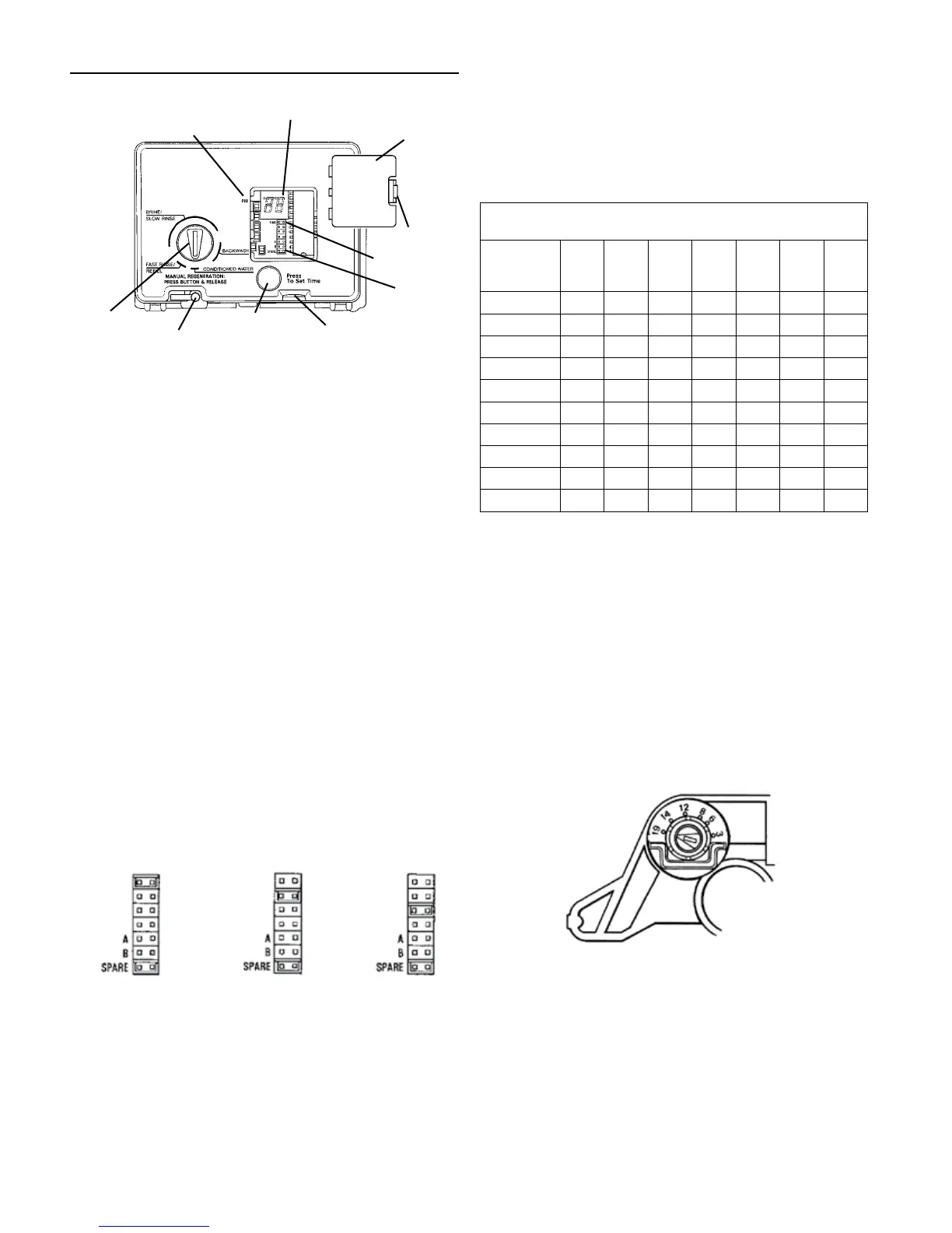
Programming
Plug the wall-mount transformer into a functioning electrical
outlet that is not controlled by a switch. Plug the transformer
into the transformer plug receptacle on the control.
Open the access door by pushing the raised tab on the door
toward the left while pulling the tab out (Figure 16).
Time of Day Setting
With the jumper on the set of pins next to the word TIME
(Figure 17), set the time of day to the closest hour by pressing
the black TIME SET button. PM hours are indicated by a light
next to the letters PM on the display window.
NOTE: The use of a small needle-nose pliers will aid in
moving the jumper.
NOTE: The unit is factory set to regenerate at 2:00 a.m. If
you prefer to have the unit regenerate at an earlier
or later time, simply set the current time of day
accordingly (e.g., to have the unit regenerate at 4:00
a.m.—two hours later—set the clock two hours
earlier than the actual time of day).
NOTE: The Timer Locking Pin should always be horizontal
(Figure 16) during operation.
Days Setting
Move the jumper to the set of pins next to the word DAYS
(Figure 18). Press the black TIME SET button until the desired
number of days between regeneration is displayed. The range
is from 1 to 30 days.
TIME
DAYS
CLOCK
TIME
DAYS
CLOCK
TIME
DAYS
CLOCK
Figure 16 Figure 17 Figure 18
Clock Setting
Move the jumper to the set of pins next to the word CLOCK
(Figure 19). Press the black TIME SET button until the desired
clock setting is displayed. The clock range is 0 to 1. Select 0
for the standard AM/PM clock or select 1 for a 24 hour clock.
Return the jumper to the top set of pins next to the word TIME
and replace the access door. The jumper must NOT be left
on any pins other than the top pair next to the word TIME.
Otherwise, the unit may show a blank display.
NOTE: A spare jumper is located on the bottom set of pins.
Common Features
When using the 255 valve with the 440i or 460i controls, there
are several features and procedures that are unique to the 400
series controls. They are as follows:
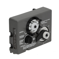
Salt Dial Adjustment
Table 1 – Suggested Salt Dial Settings (Pounds of Salt) For Various
Size Softeners
Capacity
Setting
(Kilograins)
0.5
FT
3
0.75
FT
3
1.0
FT
3
1.25
FT
3
1.5
FT
3
1.75
FT
3
2.0
FT
3
12 4.5 — — — — — —
16 9.0 5.5 — — — — —
20 — 8.5 6.0 — — — —
24 — 14.0 8.5 7.0 — — —
30 — — 15.0 11.0 9.0 — —
32 — — 18.5 12.5 10.0 9.0 —
35 — — — 16.0 12.0 10.0 9.0
40 — — — 11.5* 17.0 14.0 12.0
48 — — — — 14.0* 10.5* 17.0
60 — — — — — — 15.0*
*This setting requires the use of “XS” (extra salt) cam and
doubles the amount of the setting.
These models may be adjusted to produce maximum to
minimum conditioning capacities by setting the salt dial, which
controls the amount of salt used per regeneration. When
desired, the minimum setting may be used on installations if
the frequency of regeneration is increased to compensate for
lower regenerated conditioning capacity. The installing dealer
will set the unit for proper salt usage. Further adjustments
are needed only if the hardness of the water supply changes
or if water use changes dramatically. Capacity will need to be
adjusted accordingly.
To adjust salt dosage, insert a small screwdriver into the white
indicator knob and move pointer to proper salt setting (Figure 13).
NOTE: To convert the salt settings from English to metric,
divide by 2.2 (e.g., 12 pounds ÷ 2.2 = 5.5 kg of salt).
Figure 19
The amount of salt placed in the brine tank has nothing to do
with the amount of salt used during the regeneration cycle.
Water will dissolve and absorb salt only until it becomes
saturated. A given amount of brine (salt-saturated water)
contains a specific amount of salt. The salt dial controls the
amount of brine used during the regeneration cycle (e.g., when
set at 15 pounds (6.8 kg) the amount of brine the conditioner
will use for each regeneration will contain 15 pounds (6.8 kg)
of salt, etc.)
Never let the amount of salt in the brine tank be lower than the
normal liquid level. Do not overload the brine tank with salt.
PROGRAMMING continued
8 •AUTOTROL
®
255 Valve/400 Series Service Manual
 Loading...