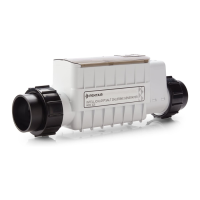
INTELLICHLOR Flow-Temperature Switch Replacement Kit Installation Guide
3
3
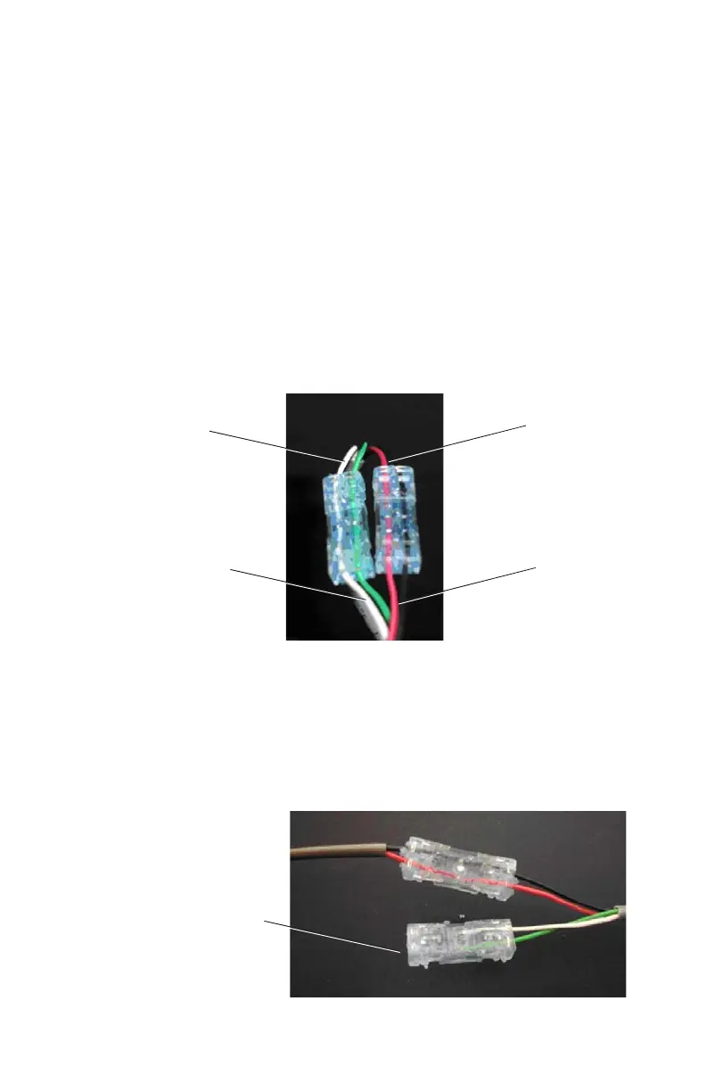
5. Insert the RED and BLACK wires from the switch into one
end of the water-tight (pair-at-a-time) connector and crimp
using pliers. Then insert the RED and BLACK wires going
into the cell into the other end of the water tight connector
and crimp using pliers. Note: Do not strip the individual
wires.
6. Insert the GREEN and WHITE wires from the switch into
one end of the second water-tight connector and crimp using
pliers. Then insert the GREEN and WHITE wires going
into the cell into the other end of second water tight
connector and crimp using pliers. Note: Do not strip the
individual wires.
7. If replacing a regular flow switch (RED and BLACK wires
only), insert green and white wires from new flow-temperature
switch into one end of the second water-tight connector and
crimp using pliers. This will provide electrical insulation for the
floating leads.
For regular flow switch
replacement, floating leads
will be covered with the
second splicer
Green and White
wires from switch
Green and
White going
into cell
Red and Black
wires from switch
Red and Black
going into cell
 Loading...