EasyManua.ls Logo

Pentair SAND DOLLAR User Manual

Pentair SAND DOLLAR
20 pages
To Next Page IconTo Next Page
Page #1 background imageLoading...
Page #1 background image
IMPORTANT SAFETY INSTRUCTIONS
READ AND FOLLOW ALL INSTRUCTIONS
SAVE THESE INSTRUCTIONS
INSTALLATION AND
USER’S GUIDE
SAND DOLLAR
®
AND CRISTAL-FLO
II
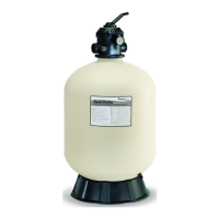
TOP MOUNT SAND FILTER
ENGLISH FRANÇAIS ESPAÑOL

Questions and Answers:

Pentair SAND DOLLAR Specifications

General IconGeneral
Filter TypeSand
Tank MaterialFiberglass
Pressure Rating50 psi
Valve MaterialPlastic
Connection Size1.5 or 2 inch
Sand Capacity100-300 lbs

Summary

Technical Support

Important Warning and Safety Instructions

Critical Safety Warnings for Installation and Use

Seriousness of bodily injury or death from incorrect installation/use.

Mandatory Reading of Instructions

Installers, operators, and owners must read all warnings and instructions.

Intended Use Specification

Specifies the sand filter is intended for swimming pool applications only.

Compliance with Local Codes

Emphasizes compliance with state/local codes for pool construction and operation.

Installer Guide Distribution

Installer notice on the guide's importance and distribution to owner/operator.

Pre-Installation Warning

Read all warnings and instructions before installation to prevent severe injury or death.

Hyperthermia and Water Temperature Hazard

Health hazards of water over 100°F, including hyperthermia and its severe effects.

Child Operation Prohibition

Prohibits children from using or operating the sand filter.

Pump Size and Flow Rate Warning

Warning against increasing pump size to avoid exceeding system flow rate limits.

High Pressure and Tank Separation Danger

Warns about severe injury/damage from high pressure and tank separation.

Pre-Work Safety Steps

Steps to take before working on the filter: stop pump, open air relief, release pressure.

Electrical Shock and Electrocution Risk

High voltage risk from pumps leading to shock, burns, or death.

Pump Servicing Electrical Safety

Disconnect power at the circuit breaker before pump servicing.

Qualified Pump Installation Requirement

Mandates qualified professional installation for pool/spa pumps to prevent electrical hazards.

Anti-Entrapment Drain Cover Mandate

Emphasizes using approved anti-entrapment drain covers and immediate action if compromised.

Virginia Graeme Baker Act Information

Provides contact information for the Virginia Graeme Baker Pool and Spa Safety Act.

Suction Outlet Safety Note

Crucial note to always turn off power before working on suction outlets or covers.

Filter Overview

High Pressure and Air Entry Hazard During Servicing

Warns about high pressure and air entry during servicing causing separation.

Safe Servicing Procedures

Details steps for safe servicing: turn off pump, open air relief, release pressure.

Filter Specifications Table

Provides specifications for tank diameter, sand, pressure, and flow rates.

Backwash Process and Filtration Role

Explains backwash process and filter's role in removing suspended matter.

Poor Water Clarity Hazard

Warns poor water clarity from filter issues can lead to serious injury or death.

Installation

Read and Understand All Instructions

Emphasizes reading and understanding all instructions prior to installation.

Proper Placement and Electrical Safety

Ensure proper placement for access and distance for electrical controls.

Component Inspection on Arrival

Inspect all components for damage upon receipt and report issues.

Suction Fitting Blockage Warning

Warns about suction fitting blockage causing drowning and prohibits children's use.

Critical Electrical Safety Measures

Critical electrical safety: disconnect power, use GFCI, and proper grounding.

Filter Positioning and Weight

Guides on positioning the filter on level ground, noting its weight when filled.

Sand Type and Lateral Inspection

Details sand type, quantity, and pre-pour inspection of filter laterals for damage.

Sand Filling Procedure

Instructions for filling the tank with water and sand, emphasizing a slow pour.

Valve Installation and Port Connections

Guides on preparing filter top and installing valve, ensuring correct port connections.

Valve Seating and Flange Contact

Instructs to ensure the valve is seated correctly against the tank flange.

Clamp Assembly Installation

Details the process of installing the clamp assembly to secure the valve to the tank.

Clamp Tightening and Inspection

Advises to tighten clamp screws and visually inspect the assembly for correct installation.

Maximum Operating Pressure Limit

Do not exceed maximum operating pressure; select appropriate pump.

Pipe Connections and Support

Use correct sealant for pipe connections and support piping.

Pressure Gauge Installation and Chemical Storage

Install pressure gauge and store chemicals safely away from equipment.

Final Electrical and Threading Precautions

Adhere to electrical safety guidelines and proper thread tightening procedures.

Operation and Maintenance

Initial Start-Up Preparations

Confirm sand amount, connections, and set valve to 'Backwash' for start-up.

Priming, Filling, and Initial Backwash

Prime pump, fill tank, and perform initial backwash to clean sand.

Rinse Cycle Procedure

Set valve to 'Rinse' and run pump to flush the system.

Filter Cycle Start-Up

Set valve to 'Filter', start pump, and check for leaks.

Pressure Monitoring and Exterior Cleaning

Monitor pressure for backwash indication and perform exterior cleaning.

Critical Safety: Never Service Under Pressure

Critical safety rule: never service filter under pressure; always relieve it first.

General Maintenance

Exterior Cleaning and Strainer Basket Maintenance

Clean filter/pump exterior and inspect pump strainer basket weekly.

Servicing Filter Under Pressure Warning

Relieve tank pressure before attempting to service the filter.

Cleaning

Initial Backwashing and Backwash Indicators

Advise initial backwashing after 48 hours and outline methods to determine need.

Flow Meter Backwash Indicator

Identifies flow meter reading a 30% decrease as an indicator for backwashing.

Visual Pool Flow Backwash Indicator

Suggests visual observation of pool flow directionals as a backwash indicator.

Pressure Gauge Backwash Indicator

Uses a 10 psi pressure increase over clean reading as a common backwash trigger.

Avoiding Timed Backwashing

Advises against timed backwashing and highlights factors affecting its frequency.

Filter and Control Valve Functions

FILTER Function Description

Explains the water path for normal filtering operation, including pump to pool.

BACKWASH Function Description

Details the flow reversal for cleaning the filter media via the waste port.

RINSE Function Description

Explains the rinse cycle for initial cleaning and resettling the filter bed.

WASTE Function Description

Details bypassing the filter for vacuuming to waste or draining the pool.

CLOSED Function Prohibition

States that the CLOSED setting should not be used while the pump is running.

RECIRCULATE Function Description

Explains bypassing the filter to circulate water without filtering it.

WINTERIZING Valve Position Reference

Refers to page 10 for information on the WINTERIZING valve position.

Filter Backwash Procedure

Poor Water Clarity Hazard Reminder

Reiteration of dangers of poor water clarity leading to injury or death.

Safety: Always Turn Off Pump Before Valve Changes

Crucial safety reminder to always turn off the pump before changing valve positions.

Step 1: Stop Pump

First step in backwashing: stop the pump.

Step 2: Prepare Lines and Set Valve to Backwash

Prepares lines and sets valve to 'Backwash' for the procedure.

Step 3: Stand Clear and Start Pump

Advises to stand clear of the filter before starting the pump.

Step 4: Backwash Duration and Clarity Check

Specifies duration and visual cue for backwashing.

Step 5: Transition to Rinse Phase

Transitioning to the rinse phase by stopping the pump and setting the valve.

Step 6: Stand Clear Before Rinse Pump Start

Reinforces standing clear before starting the pump for rinsing.

Step 7: Rinse Cycle Duration

Specifies the duration for the rinse cycle.

Step 8: Return Valve to Filter Position

Completes the backwash/rinse cycle by setting valve to 'Filter'.

Step 9: Ensure Pool Return Line is Open

Confirms the return line is open for normal filtration flow.

Step 10: Start Filter Cycle with Air Bleeder

Starts the filtering cycle by opening the air bleeder and starting the pump.

Step 11: Close Air Bleeder on Steady Stream

Details closing the air bleeder when a steady stream of water appears.

Step 12: Verify Filtering Operation and Pressure

Confirms normal filtering operation and checking the pressure.

Chemical Cleaning Trigger: Post-Backwash Pressure

Explains how to identify if chemical cleaning is needed based on post-backwash pressure.

Chemical Cleaning

Recommendation for Specialty Cleaners

Recommends specialty cleaners for removing oils, scale, and rust from the sand bed.

Follow Manufacturer's Solution Instructions

Instructs to follow the cleaning solution manufacturer's mixing instructions.

Pre-Cleaning Backwash

Advises performing a backwash before applying cleaning solution.

Safety for Filters Below Pool Level

Safety measure for filters below pool level: turn off pump and close valves.

Draining Filter and Setting Valve

Draining the filter and setting the valve to 'Backwash' before adding solution.

Post-Drainage Steps

Instructions for closing the drain and accessing the pump strainer after draining.

Ensure Backwash Lines Are Open

Confirms that backwash lines must be open for the procedure.

Adding Cleaning Solution to Pump

Details adding cleaning solution to the pump strainer while the pump is running.

Saturating the Sand Bed

Guides on adding solution until the sand bed is saturated.

Overnight Soaking Procedure

Instructs to turn off the pump and let the filter soak overnight in 'Backwash' position.

Final Cleaning Steps

Finalizes the cleaning by replacing the lid and performing a backwash.

Prevent Cleaning Solution Entering Pool

Important safety note to prevent cleaning solution from entering the pool water.

Winterizing the System

Freeze Damage Warning

Warns about damage from freezing water, leading to property damage.

Necessity of Winterization in Freezing Areas

States the necessity of winterizing equipment in freezing temperature areas.

Backwash and Set Valve to Winterize

Guides to backwash the filter and set the valve to 'Winterize' position.

Remove Drain Port Cap for Draining

Instructs to remove the drain port cap for draining.

Caution: Do Not Remove Entire Fitting

Caution on removing only the cap, not the entire fitting, to prevent sand loss.

Protect Valve Diverter Seal

Advises leaving the valve in 'Winterize' position to protect the diverter seal.

Drain All System Piping

Instructs to drain all associated system piping.

Covering Equipment (Not Motor)

Suggests covering the equipment with a tarpaulin, but not the motor.

Propylene Glycol Solution for Un-drainable Pumps

Provides guidance on using a Propylene Glycol solution for un-drainable pumps.

Anti-Freeze Solution Warning

Warning against using anti-freeze solutions other than Propylene Glycol.

Troubleshooting

Pool Water Clarity Issues

Addresses pool water clarity issues related to chemistry, backwashing, sand, and turnover.

Water Clarity Solutions

Solutions include maintaining chemistry, proper backwashing, checking sand, and adjusting run time.

High Filter Pressure Causes

High filter pressure causes: insufficient backwashing, sand plugging, or restrictions.

High Filter Pressure Solutions

Solutions for high pressure: backwash, chemical cleaning, or clearing obstructions.

Short Filter Cycles Causes

Short filter cycles causes: improper backwashing, chemistry, plugged sand, or high flow.

Short Filter Cycles Solutions

Solutions for short cycles: proper backwashing, chemistry, sand cleaning, or flow restriction.

Diminished Flow/Low Pressure Causes

Diminished flow/low pressure causes: pump/suction line obstructions.

Low Flow Solutions

Solutions for low flow: clean strainer/skimmer baskets, clear obstructions.

Sand Returning to Pool Causes

Sand returning to pool causes: broken laterals or high backwash rate.

Sand Returning to Pool Solutions

Solutions for sand return: replace laterals or reduce backwash flow rate.

Replacement Parts

1.5" Valve Replacement Parts Reference

Lists replacement parts for the 1.5" valve, referencing a breakdown page.

2" Valve Replacement Parts Reference

Lists replacement parts for the 2" valve, referencing a breakdown page.

Valve Body O-Ring Replacement

Details the replacement part for the valve body O-ring.

Clamp Assembly Replacement

Lists the replacement part for the clamp assembly.

Piping Assembly Replacements by Model

Replacement piping assemblies for various Sand Dollar/Cristal-Flo II models.

Lateral Replacements by Model

Replacement laterals for different Sand Dollar/Cristal-Flo II models.

Tank Assembly Replacements by Model

Replacement tank assemblies for various Sand Dollar/Cristal-Flo II models.

Sand Drain and Gasket Replacement

Replacement parts for the sand drain assembly and its gasket.

Drain Cap and Foot Replacements

Replacement parts for the drain cap and filter feet.

Pressure Gauge and Flex Hose Kit Replacements

Replacement pressure gauge and flex hose kits (6' and 12').

1.5" Valve Replacement Parts

1.5" Valve Handle and Screw Replacement

Replacement parts for the valve handle and its screw.

1.5" Valve Washer and Label Replacement

Replacement plastic washers and valve position label.

1.5" Valve Diverter Shaft and Top O-Rings

Replacement O-rings for the diverter shaft and valve top.

1.5" Valve Spring and Diverter Assembly

Replacement spring for the valve mechanism and diverter with gasket.

1.5" Valve Body and Diffuser Replacement

Replacement for the valve body and diffuser assembly.

1.5" Valve Air Bleeder and Clamp Assembly

Replacement air bleeder with O-ring and clamp assembly.

1.5" Valve Clamp Halves, Screws, and Nuts

Replacement clamp halves, screws, and nuts for the assembly.

1.5" Valve Fasteners and Washers

Replacement stainless steel screws, washers, and nuts.

1.5" Valve Top Assembly and Pressure Gauge

Replacement valve top assembly and pressure gauge.

1.5" Valve Sight Glass and Diffuser

Replacement sight glass, its gasket, and the diffuser.

1.5" Valve Body O-Ring and Manual

Replacement O-ring for the valve body and the valve manual.

2" Valve Replacement Parts

2" Valve Pressure Gauge Replacement

Replacement pressure gauge for the 2" valve.

2" Valve Body and Diffuser Replacement

Replacement parts for the 2" valve body and diffuser.

2" Valve Sight Glass and Drain Plug

Replacement sight glass and drain plug for the 2" valve.

2" Valve Handle and Gasket Replacement

Replacement handle and gasket for the sight glass on the 2" valve.

2" Valve Top Assembly and Drain O-Ring

Replacement valve top assembly and O-ring for the drain.

2" Valve Position Label and Union Kit

Replacement label for valve positions and union kit.

2" Valve Body O-Ring

Replacement O-ring for the 2" valve body.

Related product manuals