Do you have a question about the Pentair IntelliChlor and is the answer not in the manual?
Details the contents of the replacement kit and the initial steps for removing the old flow-temperature switch.
Instructions for correctly installing and tightening the new flow-temperature switch into the cell.
Guidance on making the proper electrical connections using the provided water-tight connectors.
Steps to complete the replacement, including wire management, cover replacement, and powering up the unit.
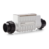
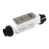
The Pentair IntelliChlor® Flow-Temperature Switch Replacement Kit is designed to replace the flow-temperature switch in an IntelliChlor® Salt Chlorine Generator, ensuring the continued safe and efficient operation of the pool's chlorine generation system. This kit provides the necessary components and instructions for users to perform the replacement themselves, maintaining the functionality of their IntelliChlor unit.
The primary function of the flow-temperature switch is to monitor both the water flow and temperature within the IntelliChlor Salt Chlorine Generator cell. This dual monitoring is crucial for the safe and effective operation of the chlorine generator. The flow sensor ensures that the unit only produces chlorine when there is sufficient water flow through the cell, preventing damage to the cell and ensuring proper distribution of chlorine in the pool. Without adequate flow, the cell could overheat or produce chlorine in a concentrated area, which is undesirable. The temperature sensor, on the other hand, monitors the water temperature. Chlorine generation is temperature-dependent, and operating the cell outside of its recommended temperature range can affect its efficiency and lifespan. By monitoring temperature, the switch helps protect the cell from extreme conditions and ensures optimal performance. When either the flow or temperature conditions are not met, the switch signals the IntelliChlor unit to cease or adjust chlorine production, thereby protecting the equipment and ensuring safety.
The replacement kit includes a new flow-temperature switch assembly and two pair-at-a-time splicers. The switch assembly is a complete unit, ready for installation. The splicers are provided to facilitate secure and watertight electrical connections for the new switch, which is essential given the wet environment of pool equipment.
The installation process for the replacement kit is detailed and designed to be followed step-by-step. Before beginning any work, it is critical to switch off power to both the pool pump and the IntelliChlor Salt Chlorine Generator cell. This safety precaution prevents electrical shock and damage to the equipment during the replacement procedure. The first step in the actual replacement involves removing the existing flow-temperature switch from the IntelliChlor cell. This begins with removing the flow switch cover, which typically protects the internal components. Once the cover is off, the flow-temperature switch cable, which is usually wrapped around the switch nut, needs to be loosened. Users are advised to note the direction of the arrows on top of the switch nut, as this will be important for proper reinstallation. The cable is then cut close to the switch, ensuring enough wire remains for the new switch cable to be connected. A flat 1-3/16" (30 mm) wrench is used to carefully unscrew the old flow-temperature switch assembly from the cell. Caution is advised during this step to avoid damaging the cell's plastic coupling with the wrench.
Once the old switch is removed, the installation of the new replacement flow-temperature switch begins. The new switch is inserted into the threaded hole in the cell and hand-tightened as much as possible. Following this, the same flat 1-3/16" (30 mm) wrench is used to carefully tighten the flow-temperature switch assembly until its thread is nearly bottomed out. A crucial step for correct operation is to tighten the switch nut so that the arrows on its top point in the direction of water flow, and the center arrow is aligned in the center position. This ensures the flow sensor is correctly oriented to detect water movement.
Electrical connections are then made using the provided splicers. The cable jacket of the wires that were cut from the unit needs to be stripped back, but it is explicitly stated not to strip the individual wires. The RED and BLACK wires from the new switch are inserted into one end of a water-tight connector and crimped using pliers. Similarly, the RED and BLACK wires going into the cell are inserted into the other end of the same connector and crimped. The same process is repeated for the GREEN and WHITE wires using the second water-tight connector. This method ensures secure and insulated connections for all wires. For cases where a regular flow switch (with only RED and BLACK wires) is being replaced by the new flow-temperature switch, the green and white wires from the new switch are inserted into one end of the second water-tight connector and crimped. This provides electrical insulation for these "floating" leads, even if they are not actively used in the older system, ensuring safety and preventing potential issues. The second splicer is then used to cover these floating leads for regular flow switch replacements.
After the electrical connections are made, the excess wire is wrapped around the flow switch, and the flow switch cover is replaced. These steps help to organize the wiring and protect the connections from the elements. Finally, the IntelliChlor® Salt Chlorine Generator is ready for operation. The last step is to switch the power back on to both the pool pump and the IntelliChlor Salt Chlorine Generator cell.
The IntelliChlor® Salt Chlorine Generator is designed to provide a continuous supply of pure chlorine for pool sanitation. The flow-temperature switch is an integral part of this system, ensuring that chlorine is generated only under optimal conditions. By maintaining proper flow and temperature, the switch helps to extend the life of the electrolytic cell, which is the core component responsible for converting salt into chlorine. Regular maintenance, including the replacement of components like the flow-temperature switch when necessary, is key to the longevity and efficiency of the entire system. The user-friendly design of the replacement kit and the clear instructions aim to empower pool owners to perform these essential maintenance tasks, thereby reducing the need for professional service and ensuring uninterrupted enjoyment of a clean and healthy pool. The IntelliChlor system, with its integrated safety features like the flow-temperature switch, represents a reliable and convenient method for pool chlorination, eliminating the need for traditional chlorine tablets or liquid chlorine.
| Type | Salt Chlorine Generator |
|---|---|
| Salinity Range | 2500 - 4500 ppm |
| Cell Life | 10, 000 hours |
| Flow Rate | 20 GPM minimum, 80 GPM maximum |
| Power | 240V AC, 50/60Hz |
| Chlorine Output | Varies by model (IC15, IC20, IC40, IC60 - corresponding to grams of chlorine produced per day) |