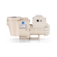
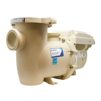
IntelliFlo VF Installation and User’s Guide
FIELD WIRING COMPARTMENT CONNECTIONS
L1 = HOT LEAD
L2 = HOT LEAD
GREEN SCREW = GROUND LEAD
Wiring the IntelliFlo VF (for models with side AC Power connection)
NOTE THIS WORK MUST BE DONE BY THE QUALIFIED ELECTRICIAN in accordance with the
national wiring rules (AS/NZS 3000) taking into account its ratings (Class I, IPX5).
NOTE
— Use only RCD/ELCB suitable for protecting equipment with a DC current content in the fault
current.
circuit breaker2-pole timer or 2-pole relay
IMPORTANT: When connecting the pump to an automation system (IntelliComm), continuous
power must be supplied to the pump by connecting it directly to the circuit breaker. When using an
automation system, Be sure that no other lights or appliances are on the same circuit.
NOTE: When the IntelliFlo VS is started and stopped by removing power with a relay or timer, a
two-pole device should be used to apply and remove power to both POWER LINE TERMINALS.

 Loading...
