5
S536 (11-25-19)
INSTALLATION
DISCHARGE PIPE SIZES
1. If increasing discharge pipe size, install reducer in pump discharge
port. Do not increase pipe size by stages.
2. When the pump is set away from the points of water use, the
discharge pipe size should be increased to reduce pressure losses
caused by friction.
• Up to 100’ run: Same size as pump discharge port.
• 100’ to 300’ run: Increase one pipe size.
• 300’ to 600’ run: Increase two pipe sizes.
LAWN SPRINKLING APPLICATION
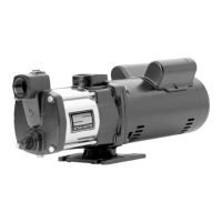
This pump is designed for lawn sprinkling. It is de signed to deliver
plenty of water at full sprinkler pres sure. It can pump from a pond,
cistern or well points.
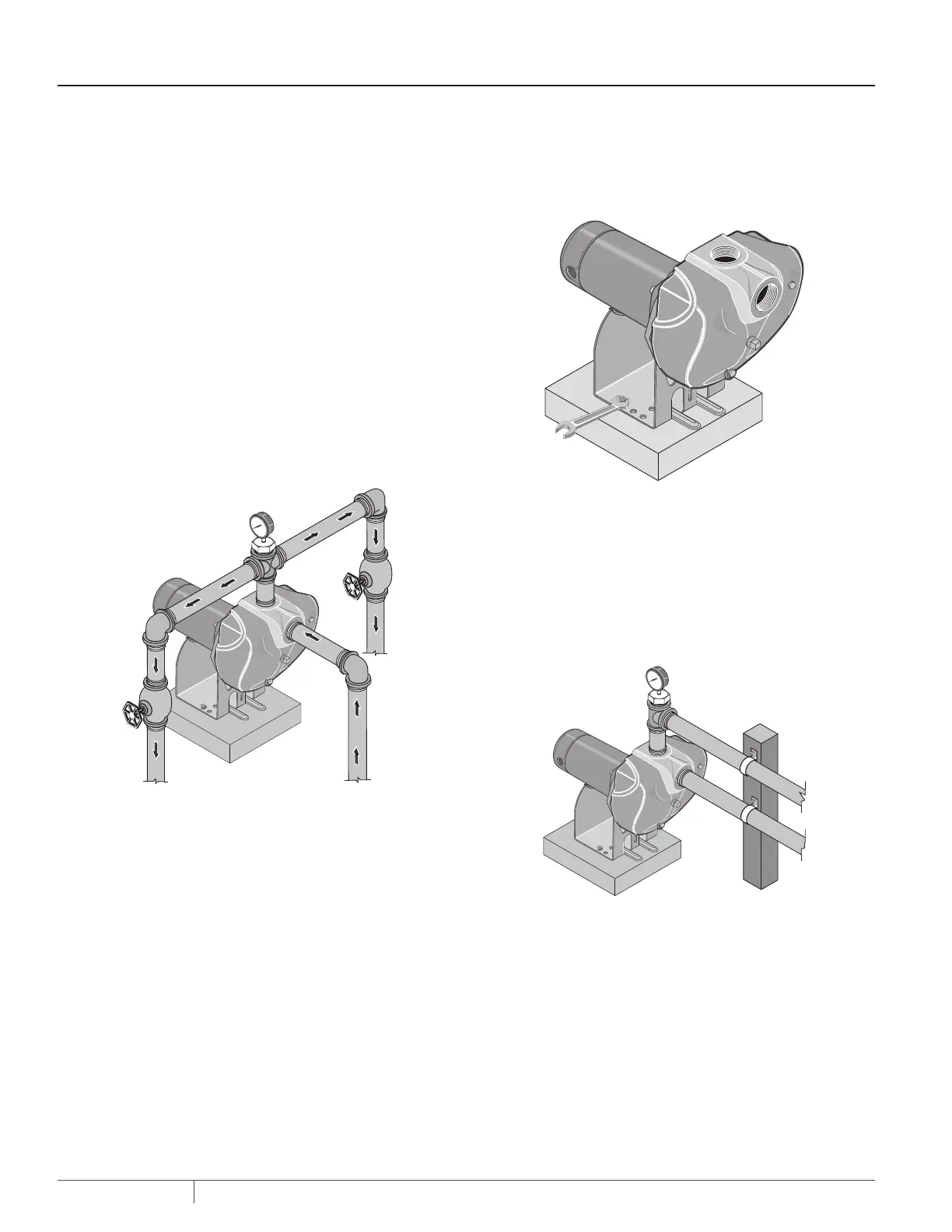
Pump discharge can be divided to supply two (2) or more sprinkler
systems. A suggested multiple dis charge to service is shown in
Figure 3.
Do not use in a pressure tank or booster pump application.
20
100
80
60
40
PUMP INSTALLATION
1. Install pump as close to well head as poss ible. Long piping runs
and many fittings create friction and reduce flow.
2. Bolt pump to solid, level foundation as shown in Figure 4.
3. Support all piping connected to the pump (Figure 5).
NOTICE: For long horizontal pipe runs, install a priming tee between
check valve and well head (Figure 1). For driven point installations,
install a check valve (Figure 2). Be sure check valve flow arrow points
toward pump.
Use schedule 80 or iron pipe. See “Well Pipe In stalla tion” for more
information.
20
100
80
60
40
4. Wrap 1-1/2 to two layers of PTFE pipe thread sealant tape
clockwise (as you face end of pipe) on all male threads being
attached to pump.
Ensure all suction pipe joints are air and water tight so the pump
can pull water from the well.
5. Tighten joints hand tight plus 1-1/2 turns. Do not overtighten.
NOTICE: Install pump as close to well head as poss ible. Long piping
runs and many fittings create friction and reduce flow.
Figure 3: Multiple Discharge
Figure 4: Bolt Pump Down
Figure 5: Independently Support All Piping
Attached to Pump

 Loading...