Functional Safety KCD2-UT2-(Ex)1, HiC2081
Product Description
2018-02
7
2 Product Description
2.1 Function
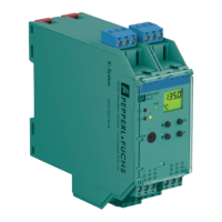
KCD2-UT2-1
This signal conditioner provides the galvanic isolation between field circuits and control
circuits.
The device converts RTD input signals or thermocouple input signals on the field side to
0/4 mA ... 20mA signals on the control side.
The removable terminal block KC-CJC-** is available for thermocouples when internal cold
junction compensation is desired.
A fault is indicated by an LED and by user-configured fault indication outputs.
If the device is operated via Power Rail, additionally a collective error message is available.
The device is easily configured by the use of the PACTware configuration software.
The device is mounted on a 35 mm DIN mounting rail according to EN 60715.
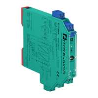
KCD2-UT2-Ex1
This isolated barrier is used for intrinsic safety applications.
The device converts RTD input signals or thermocouple input signals in the hazardous area to
0/4 mA ... 20mA signals in the safe area.
The removable terminal block KC-CJC-** is available for thermocouples when internal cold
junction compensation is desired.
A fault is indicated by an LED and by user-configured fault indication outputs.
If the device is operated via Power Rail, additionally a collective error message is available.
The device is easily configured by the use of the PACTware configuration software.
The device is mounted on a 35 mm DIN mounting rail according to EN 60715.
HiC2081
This isolated barrier is used for intrinsic safety applications.
This device accepts thermocouples (TC), millivolts, potentiometers, or resistance temperature
detectors (RTD) from a hazardous area and converts them to an isolated, linearized analog
output in the safe area.
The output can be selected as a current source or current sink with a switch.
Line fault detection of the field circuit is indicated by a red LED and an output on the fault bus.
The fault conditions are monitored via a Fault Indication Board.
The device is easily configured by the use of the PACTware configuration software.
This device mounts on a HiC Termination Board.