SAFETY MANUAL SIL KFD2-UT2-(EX)*, HID2082
Proof Test
2011-09
15
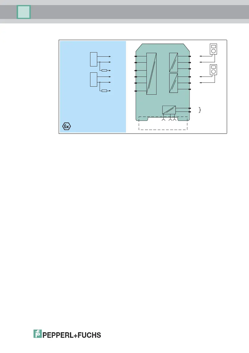
Thermocouple Input (TC)
Figure 4.1 Example proof test set-up for KFD2-UT2-(Ex)* (TC)
Usage in Zone 0, 1, 2/Div. 1, 2 only for KFD2-UT2-Ex1 and KFD2-UT2-Ex2
1-channel versions KFD2-UT2-1 and KFD2-UT2-Ex1 have only one channel.
Additional set up: 110 Ω fixed resistor
1. Connect TC simulator to the input terminals 1+ and 2- (channel I) and
4+ and 5- (channel II).
2. Connect current meter/digital multimeter (DMM) to the current output
terminals 7 and 8 (channel I) and 10 and 11 (channel II).
3. Set compensation/reference temperature in the simulator to 26 °C.
4. Connect a 110 Ω fixed resistor (0.1 % accuracy) to terminals 2 and 3
(channel I) and 5 and 6 (channel II) (instead of the special sensor for internal
compensation).
5. Set the TC simulator sequentially to the temperature values
representing 4 mA, 12 mA, 20 mA and measure the output current.
6. Proof test is passed if the measured output values are within 2 % of the output
span. This means:
• 3.7 mA ... 4.3 mA
• 11.7 mA ... 12.3 mA
• 19.7 mA ... 20.3 mA
7. Remove the 110 Ω resistor from terminals 2 and 3 (channel I) and 5 and 6
(channel II), to check if the lead breakage of the CJC is monitored. The red
LED must be blinking. The output behaviour in the event of a failure depends
on the device configuration.
This test is also applicable if external compensation (setting of a fixed
compensation temperature in the module) is used in the application. Adapt
CJC value in the simulator during step 3 accordingly.
KFD2-UT2-Ex2
Zone 2
Div. 2
Zone 0, 1, 2
Div. 1, 2
2
3
1
5
6
4
24 V DC
14+
15-
Power Rail
24 V DCERR
7
9-
8+
10
12-
11+
mA
mA
110Ω
TC
Sim.
110Ω
TC
Sim.
 Loading...


