2011-09
18
SAFETY MANUAL SIL KFD2-UT2-(EX)*, HID2082
Proof Test
Voltage Input (mV)
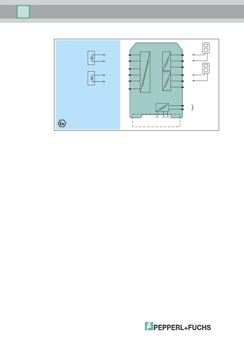
Figure 4.3 Example proof test set-up for KFD2-UT2-(Ex)* (TC)
Usage in Zone 0, 1, 2/Div. 1, 2 only for KFD2-UT2-Ex1 and KFD2-UT2-Ex2
1-channel versions KFD2-UT2-1 and KFD2-UT2-Ex1 have only one channel.
1. Connect mV source to terminals 1 and 2 (channel I) and 4 and 5 (channel II).
2. Connect current meter/digital multimeter (DMM) to the current output
terminals 7 and 8 (channel I) and 10 and 11 (channel II).
3. Set the mV source sequentially to the voltage values
representing 4 mA, 12 mA, 20 mA and measure the output current.
4. Proof test is passed if the measured output values are within 2 % of the output
full scale. This means:
• 3.7 mA ... 4.3 mA
• 11.7 mA ... 12.3 mA
• 19.7 mA ... 20.3 mA
Additionally the loop diagnosis shall be tested to prove that the fault signalling via
the current output is working correctly. The output current in the event of a failure
depends on the device configuration. Please record this configuration and the
resulting expected fault signalling current in the test report. Example: if downscale
is configured, 2.0 mA ±1 % must be measured in the event of a failure. The red
LED must be blinking.
Voltage Input:
■ Disconnect voltage source. Verify that the output indicates a lead breakage.
KFD2-UT2-Ex2
Zone 2
Div. 2
Zone 0, 1, 2
Div. 1, 2
2
3
1
5
6
4
24 V DC
14+
15-
Power Rail
24 V DCERR
7
9-
8+
10
12-
11+
mA
mA
mV
+
-
mV
+
-
 Loading...


