Functional Safety KFD2-UT2-(Ex)*(-1)
Operation
2019-10
19
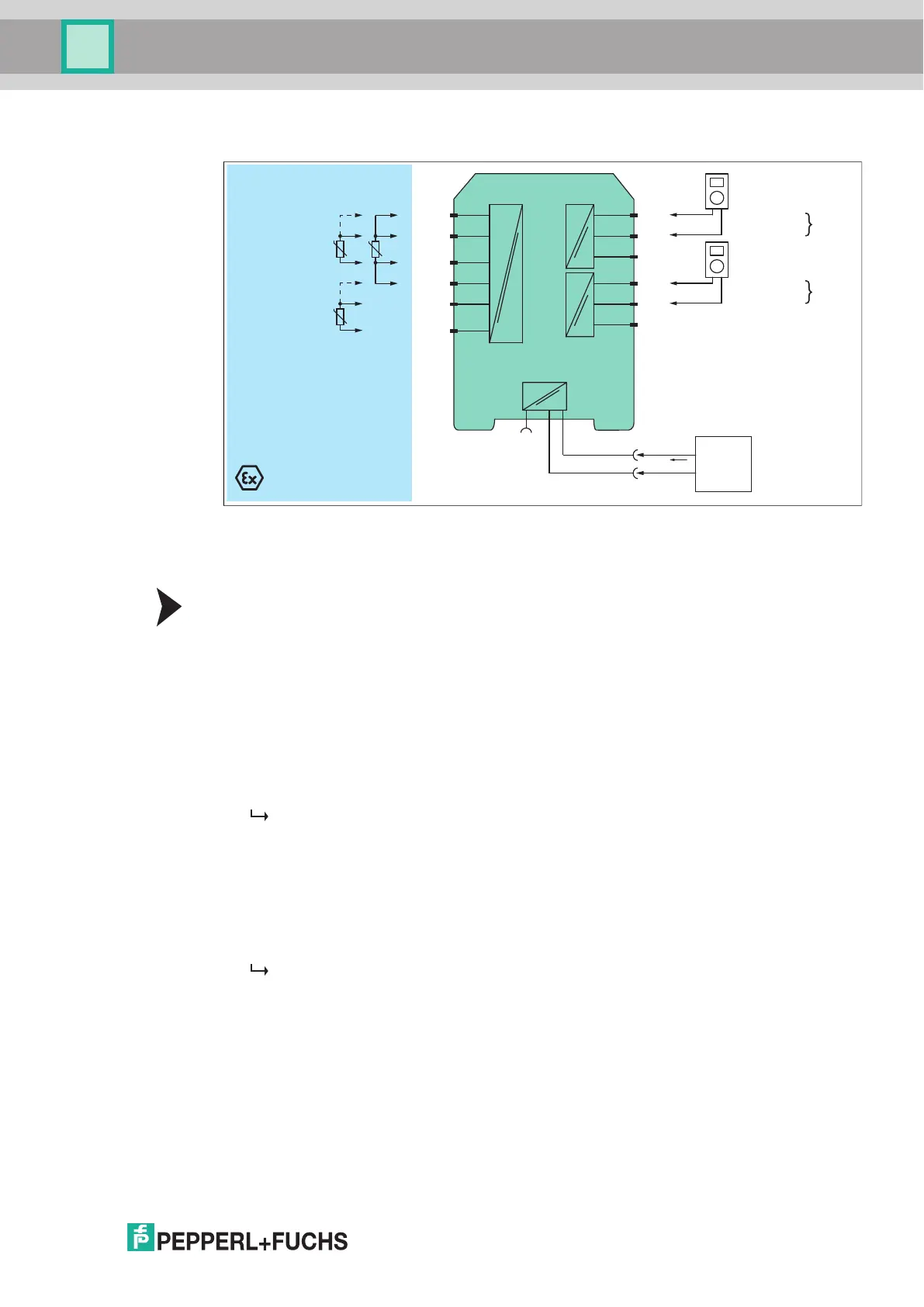
5.2.2 Resistance Thermometer Input (RTD)
Figure 5.2 Proof test set-up for KFD2-UT2-(Ex)*(-1) with resistance thermometer input (RTD)
Usage in Zone 0, 1, 2/Div. 1, 2 only for KFD2-UT2-Ex1(-1) and KFD2-UT2-Ex2(-1)
1-channel versions KFD2-UT2-1(-1) and KFD2-UT2-Ex1(-1) have only one channel.
Proof Test Procedure
1. Connect a RTD simulator, depending on the application.
• for 4-wire connection: terminals 1, 2, 3, 4
• for 3-wire connection: terminals 1, 2, 3 (channel I) and 4, 5, 6 (channel II)
• for 2-wire connection: terminals 2, 3 (channel I) and 5, 6 (channel II)
2. Connect the digital multimeter terminals 7 and 8 (channel I) and 10 and 11 (channel II).
3. Set the RTD simulator sequentially to the temperature values
representing 4 mA, 12 mA, 20 mA at the output.
4. Measure the output current.
The proof test is passed if the output values are within 2 % of the output span.
1
This means:
– for the 4 mA application: 3.7 mA to 4.3 mA
– for the 12 mA application: 11.7 mA to 12.3 mA
– for the 20 mA application: 19.7 mA to 20.3 mA
5. Apply short circuit between terminals 2 and 3 (channel I) and between
terminals 5 and 6 (channel II). Do not remove the RTD simulator. Check if a short circuit
of the cold junction compensation is detected.
The red LED is flashing. The output behavior in the event of a fault depends
on the device configuration.
KFD2-UT2-Ex2
Zone 0, 1, 2
Div. 1, 2
Zone 2
Div. 2
T
T
T
2
3
1
5
6
4
7
9-
8+
10
12-
11+
Fault
I supply
Multimeter
(mA)
Multimeter
(mA)
I
II
Supply +
Supply -
24 V DC
Power
supply
Supply
Bus
1
Additionally the loop diagnosis shall be tested to prove that the fault signaling via the current output is working
correctly. The output current in the event of a failure depends on the device configuration. Please record
this configuration and the resulting expected fault signaling current in the test report. Example: if downscale
is configured, 2.0 mA ±1 % must be measured in the event of a failure. The red LED must be flashing.