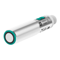
Ultrasonic sensor UC2000-L2-E6-V15
3
Release date: 2014-01-08 10:03 Date of issue: 2014-01-08 188202_eng.xml
Germany: +49 621 776 4411Pepperl+Fuchs Group
Refer to “General Notes Relating to Pepperl+Fuchs Product Information”.
USA: +1 330 486 0001 Singapore: +65 6779 9091
www.pepperl-fuchs.com fa-info@us.pepperl-fuchs.com fa-info@sg.pepperl-fuchs.com
fa-info@de.pepperl-fuchs.com
Description of Sensor Functions
Programming procedure
The sensor features two outputs with two programmable switch points, each (for a total of 4). Programming the switch points and the operating mode can be done in two
different ways:
- via the sensor’s programming buttons
- via the serial interface, which requires an external interface adapter
The procedure for programming via the sensor's programming buttons is described below. For programming using the serial interface, please refer to the software manual.
Switch points and operating modes of each output can be programmed independently without influencing each other.
Note:
- Programming is enabled for 5 minutes after power-on. After 5 minutes without programming activity the programming feature will be locked.
- During any programming step it is possible to leave the programming routine without changing the sensor settings by pressing the currently used programming button
for 10 s.
Programming the Switch Points
Notes:
- The description below leads you through programming output 1’s switch points. The procedure for output 2 is exactly the same with the only difference, being to use the
Programming Button T2.
- If the red LED flashes during the programming procedure, it indicates uncertain target detection. In this case, please correct the target alignment until the yellow LED
flashes. The new settings will only be stored in the sensor’s memory if the yellow LED flashes.
Programming the Near Switch Point
1. Place the target at the desired near switch point position
2. Press Programming Button T1 for 2 s (corresponding yellow LED flashes)
3. Press Programming Button T1 briefly (green LED flashes three times for confirmation). The sensor returns to normal operation.
Programming of the Far Switch Point
1. Place the target at the desired far switch point position
2. Press Programming Button T1 for 2 s (corresponding yellow LED flashes)
3. Press Programming Button T1 for 2 s (green LED flashes three times for confirmation). The sensor returns to normal operation.
Programming Modes of Operation
Note:
The description below leads you through programming of the modes of operation for output 1. The procedure for output 2 is exactly the same with the only difference,being to
use Programming Button T2.
The sensor provides a three step routine to program the modes of operation. In this routine you can program:
1. Output function
2. Output behavior
3. Beam width
Programming the modes is carried out sequentially. To toggle from one mode to the next, press the Programming button for 2 s.
Press Programming Button T1 for 5 s to enter the operating modes programming routine.
Programming the output function
1. The green LED flashes. The number of flashes indicates the current output function:
single flash: Switch point output function
double flash: Window output function
triple flash: Hysteresis output function.
2. Press Programming Button T1 briefly to toggle sequentially through these output functions and select the desired mode.
3. Press Programming Button T1 for 2 s to save and enter the programming routine for output behavior
Programming the output behavior
1. The yellow LED flashes. The number of flashes indicates the current output behavior:
single flash: Normally Open (NO)
double flash: Normally Closed (NC).
2. Press Programming Button T1 briefly to toggle sequentially through these output behaviors and select the desired mode.
3. Press Programming Button T1 for 2 s to save and enter the programming routine for beam width.
Programming the beam width
1. The red LED flashes. The number of flashes indicates the current beam width setting:
single flash: narrow
Accessories
PACTware 3.6
FDT-Framework
PACTware 4.X
FDT-Framework
Ultraschall-Sensoren DTM
DTM devices for communication with cube style and UMC... sensors
UC-PROG1
Programming adapter
V15-G-2M-PVC
Female cordset, M12, 5-pin, PVC cable
V15-W-2M-PUR
Female cordset, M12, 5-pin, PUR cable
Microsoft .NET
 Loading...