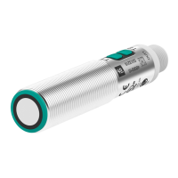
Ultrasonic sensor UC2000-L2-E6-V15
4
Release date: 2014-01-08 10:03 Date of issue: 2014-01-08 188202_eng.xml
Germany: +49 621 776 4411Pepperl+Fuchs Group
Refer to “General Notes Relating to Pepperl+Fuchs Product Information”.
USA: +1 330 486 0001 Singapore: +65 6779 9091
www.pepperl-fuchs.com fa-info@us.pepperl-fuchs.com fa-info@sg.pepperl-fuchs.com
fa-info@de.pepperl-fuchs.com
double flash: medium
triple flash: wide.
2. Press Programming Button T1 briefly to toggle sequentially through these beam shapes.
3. Press Programming Button T1 for 2 s to save and exit the operating modes programming routine.
Note:
Independently programming the beam width for each individual output is not possible. The last programmed beam width is valid for both outputs. It doesn’t matter which Pro-
gramming Button is used.
Reset Sensor to Factory Settings
The sensor has a feature to reset to factory settings
1. Disconnect the sensor from power supply
2. Press and hold one of the Programming Buttons T1 or T2
3. Connect Sensor to power supply (red and yellow LED flash simultaneously for 5 s then green and yellow LED flash simultaneously)
4. Release Programming Button
The sensor now operates with default factory settings.
Factory settings
See technical data.
Display
The sensor is provided with LEDs to indicate various conditions.
#
*)
off if yellow LED out2 is on
Synchronization
This sensor features a synchronization input for suppressing ultrasonic mutual interference ("cross talk"). If this input is not connected, the sensor will operate freewheeling
using internally generated clock pulses. It can be synchronized by applying an external square wave or by means of appropriate programming via the serial interface. Each
falling edge of the synchronization pulse triggers transmission of a single ultrasonic pulse. If the synchronization signal remains low for ≥ 1 second, the sensor will revert to
normal operating mode. Normal operating mode can also be activated by opening the signal connection to the synchronization input.(See note below)
If the synchronization input goes to a high level for > 1 second, the sensor will switch to standby mode, indicated by the green LED. In this mode, the output(s) will remain in
the last valid output state. When using the external synchronization feature, please refer to the software description.
Note:
If the option for synchronization is not used, the synchronization input has to be connected to ground (0V) or the sensor has to be operated via a V1 cordset (4-pin).
The synchronization function cannot be activated during programming mode and vice versa.
The following synchronization modes are possible:
1. Several sensors (max. number see technical data) can be synchronized together by interconnecting their respective synchronization inputs. In this case, each sensor
alternately transmits ultrasonic pulses in a self multiplexing mode. No two sensors will transmit pulses at the same time. (See note below)
2. Several sensors (max. number see technical data) can be synchronized together by interconnecting their respective synchronization inputs. Due to programming via the
sensors interface one sensor acts as a master device, all the others as slave devices. (see description of the interface) In this master / slave mode the sensors are triggered
in parallel and are synchronized by a common synchronization pulse, provided by the master device.
3. Multiple sensors can be controlled by the same external synchronization signal. In this mode the sensors are triggered in parallel and are synchronized by a common
external synchronization pulse. All sensors must be parameterized for external synchronization by means of the sensor interface. See software description.
4. A separate synchronization pulse can be sent to each individual sensor. In this mode the sensors operate in external multiplex mode. (See note below). All sensors must
be parameterized for external synchronization by means of the sensor interface. See software description.
5. A high level (+U
B
) or a low level (-U
B
)on the synchronization input switches the sensor to standby mode if it is parameterized for external synchronization.
Note:
Sensor response times will increase proportionally to the number of sensors that are in the synchronization string. This is a result of the multiplexing of the ultrasonic transmit
and receive signal and the resulting increase in the measurement cycle time.
Note:
The sensors syncronization input delivers an output current in case of low level and burdens with its input impedance in case of high level. Please pay attention that the syn-
chronizing device needs to have that driver capability:
driver current against +U
B
≥ n * high-level/input impedance (n = number of sensors to be synchronized)
driver current against 0V ≥ n * output current (n = number of sensors to be synchronized).
Green LED Yellow LED out1 / out2 Red LED
During Normal operation
Proper operation
Interference (e.g. compressed air)
On
*)
Off
Switching state
output 1 / output 2
remains in previous state
Off
On
During Switch Point Programming
Object detected
No object detected
Confirmation after Programming
Programming failed warning
Off
Off
Triple flashing
Off
Flashing
Off
Off
Off
Off
Flashing
Off
Triple flashing
During Sensor Mode Programming
Programming the output function
Programming the output behaviour
Programming the beam width
Flashing
Off
Off
Off
Flashing
Off
Off
Off
Flashing
 Loading...