EasyManua.ls Logo

Perfect Aire 2PAMSHQC12-17.5 User Manual

Perfect Aire 2PAMSHQC12-17.5
89 pages
To Next Page IconTo Next Page
Page #1 background imageLoading...
Page #1 background image
z
Revision A2: 160527001, Content updated.
Aurora MONO Split DC Inverter
Air Conditioner
SERVICE MANUAL
Table of Contents
1. Precaution
2. Part Names And Functions
3. Dimension
4. Refrigerant Cycle Diagram
5. Wiring Diagram
6. Installation Details
7. Operation Characteristics
8. Electronic Function
9. Troubleshooting
10. Disassembly Instructions
WARNING
Installation MUST conform with local building codes or, in the absence of local codes, with the
National Electrical Code NFPA70/ANSI C1-1993 or current edition and Canadian Electrical
Code Part1 CSA C.22.1.
The information contained in the manual is intended for use by a qualified service technician
familiar with safety procedures and equipped with the proper tools and test instruments
Installation or repairs made by unqualified persons can result in hazards to you and others.
Failure to carefully read and follow all instructions in this manual can result in equipment
malfunction, property damage, personal injury and/or death.
This service is only for service engineer to use.
Model Numbers:
MSABB-12HRDN1-BP0Q1W, MSABD-18HRDN1-MP0Q1W, MSABE-23HRDN1-MP0Q1W,
MSABF-36HRFN1-MP0Q1W(B)
PERFECT AIRE
QUICK CONNECT MINI-SPLIT
2ND GENERATION
2PAMSHQC12-17.5
2PAMSHQC18-16
2PAMSHQC24-16
2PAMSHQC36-16
Question and Answer IconNeed help?

Do you have a question about the Perfect Aire 2PAMSHQC12-17.5 and is the answer not in the manual?

Perfect Aire 2PAMSHQC12-17.5 Specifications

General IconGeneral
BrandPerfect Aire
Model2PAMSHQC12-17.5
CategoryAir Conditioner
LanguageEnglish

Summary

Crucial Safety Information

General Safety Precautions and Warnings

Essential instructions to prevent injury and property damage during operation and installation.

Product Identification and Specifications

Precautionary Measures

Details safety guidelines and critical warnings for safe use and installation.

Model Nomenclature

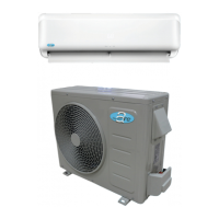
Lists indoor and outdoor unit model names based on series and capacity.

Unit Dimensions and Clearances

Diagrams showing clearance requirements for indoor and outdoor units.

Indoor Unit Dimensions and Mounting

Provides dimensions and mounting plate details for indoor units.

Outdoor Unit Dimensions and Clearances

Illustrates clearance requirements and provides dimensional data for outdoor units.

System Diagrams and Installation Procedures

Refrigerant Cycle Diagram

Illustrates the refrigerant flow for cooling and heating modes.

Wiring Diagram Reference

Note to refer to the unit for the wiring diagram.

Detailed Installation Steps

Covers torque specs, cable selection, refrigerant charging, evacuation, and re-installation.

Electronic Functions, Operation, and Protection

Abbreviation Glossary

Defines abbreviations for various temperature sensors and parameters.

Indoor Display and Icon Explanations

Explains indoor display icons and digital display meanings.

Compressor and Fan Protection Mechanisms

Details protection functions for compressor, fan, and inverter modules.

Operation Modes and Fan Speed Control

Describes fan modes, cooling/heating rules, and fan speed control.

Troubleshooting and Error Code Diagnosis

Capacitor Discharge Safety Procedure

Warning about residual electricity in capacitors and safe discharging methods.

Indoor Unit Error Display Codes

Lists indoor unit error codes, their status, and potential causes.

Outdoor Unit PCB and LED Status Indicators

Maps outdoor unit LED status to problems and IU display codes.

Component Failure Diagnosis and Solutions

Diagnoses and solutions for EEPROM, communication, and sensor errors.

System Protection Error Diagnosis and Solutions

Troubleshooting for overload, voltage, and pressure protection errors.

Inverter and Fan Speed Error Diagnosis and Solutions

Diagnoses for inverter compressor drive and fan speed control errors.

Disassembly and Component Removal Instructions

Indoor Unit Panel and Evaporator Removal

Steps to remove the front panel, electrical parts, and evaporator from the indoor unit.

Indoor Unit Fan Motor Removal

Procedure to remove the fan motor and fan assembly from the indoor unit.

Outdoor Unit Panel and Fan Assembly Removal

Guide to removing outdoor unit panel plates and fan assembly.

Outdoor Unit Electrical Parts and Valve Removal

Steps to remove outdoor electrical parts, four-way valve, and compressor.

Related product manuals